本文主要是介绍基于simscape的多体建模,希望对大家解决编程问题提供一定的参考价值,需要的开发者们随着小编来一起学习吧!
基于simscape的多体建模
1 简单介绍
从MATLAB命令行新建一个simscape的.slx文件:
smnew %simulink new
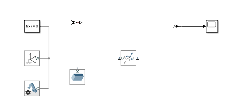
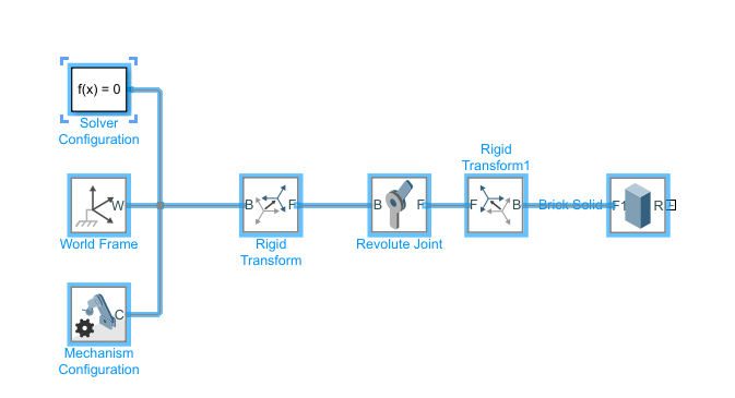
s i m s c a p e simscape simscape必不可少的三部分:求解器 f ( x ) = 0 f(x)=0 f(x)=0,世界坐标系 w o r l d f r a m e world \,\,frame worldframe以及 m e c h a n i c a l mechanical mechanical c o n f i g u r a t i o n configuration configuration。在求解器里可以设置容忍误差,在 m e h a n i c a l c o n f i g u r a t i o n mehanical \,\,configuration mehanicalconfiguration里可以设置重力加速度的大小和方向。
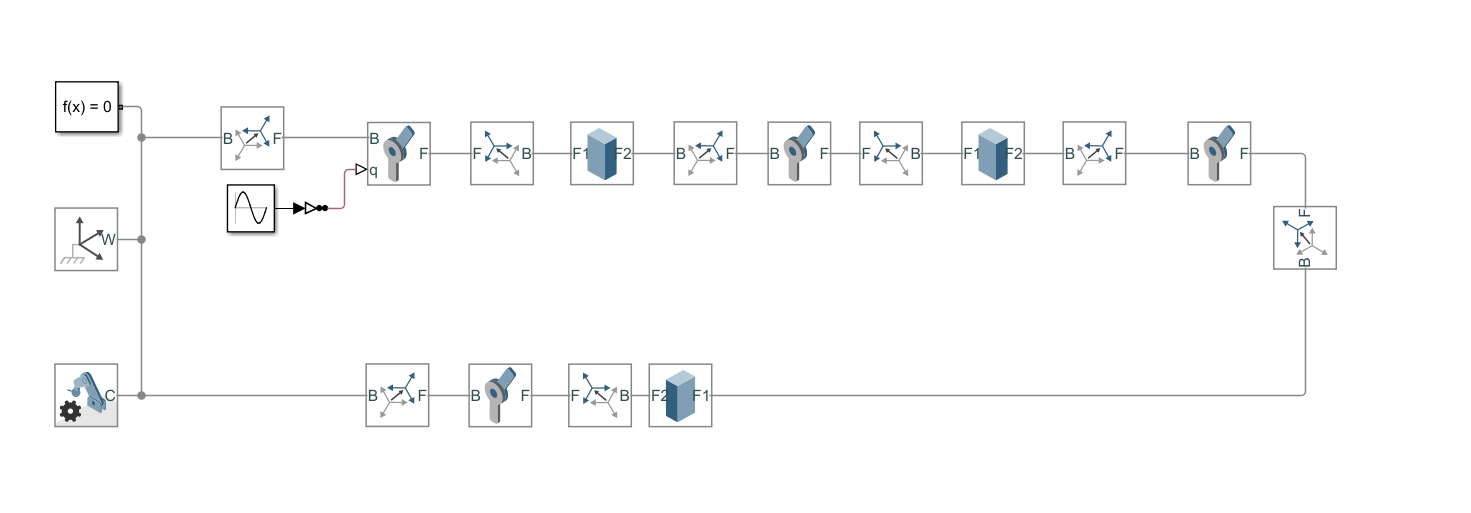
2 四连杆机构建模
使用软件设定好的重力加速度(沿Z轴负方向,大小为9.80665)和容忍误差。在simscape环境下仿真的模型可以通过两种方式获得,一种是直接在simscape中利用Multibody进行建模,还有一种方式是从外部直接导入模型。从外部导入模型(一般零部件格式为.stl)有两种操作方式,一个是借助urdf文件导入模型,另一种是用Multibody的File solid模块导入模型,使用urdf有个好处就是使用一行代码smimport("test.urdf")便可以实现建模,而单纯使用File solid模块导入模型时会涉及到复杂的坐标变换问题。当然,撰写urdf文件是件麻烦事,不过它通用性好,一次写完,可多个平台使用。
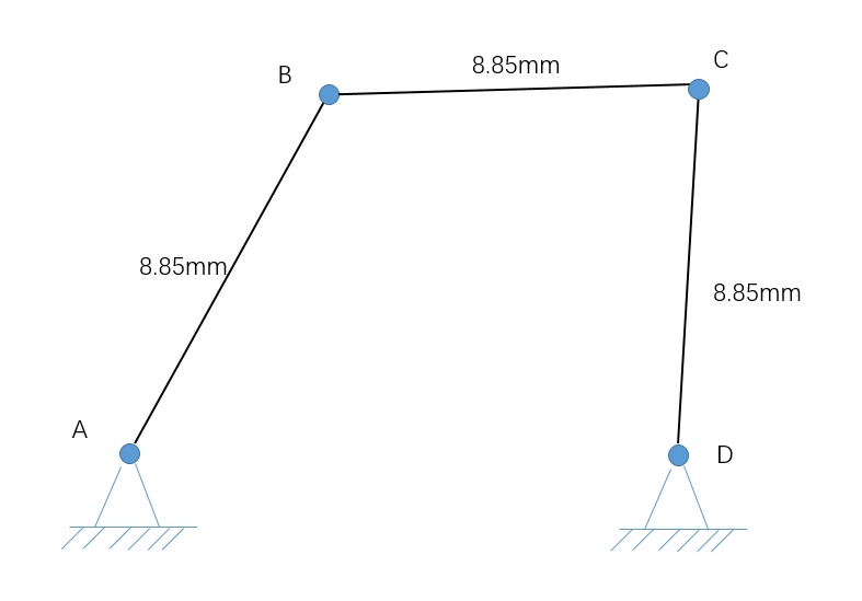
这里直接在simscape环境下进行建模,搭建一个简单的四连杆机构来展示一个simscape建模过程。要搭建的模型如图所示:
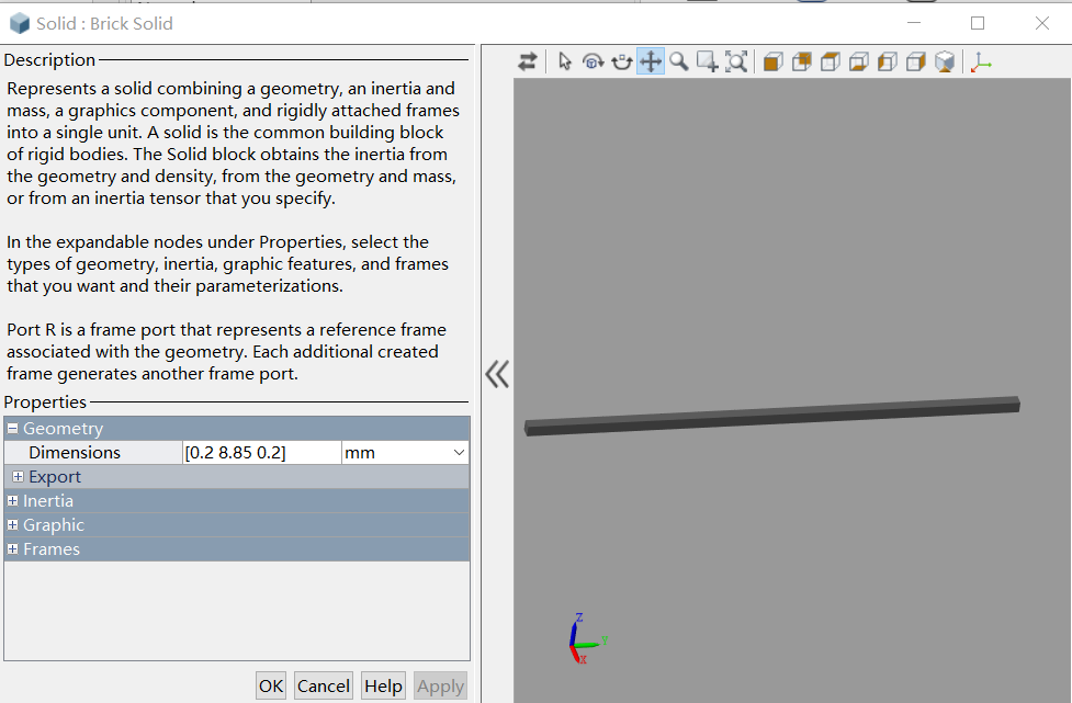
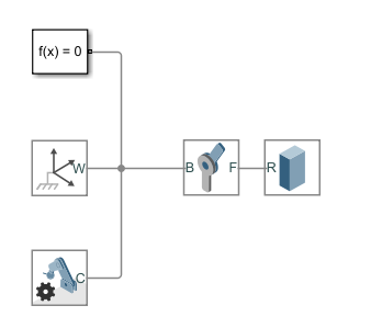
首先利用Brick Solid模块搭建一个长8.85mm的杆,如图figure 2.2所示。
这篇关于基于simscape的多体建模的文章就介绍到这儿,希望我们推荐的文章对编程师们有所帮助!


