本文主要是介绍信号处理(一)Synchronous detection同步检波(FFT,HPF,AM,FM),希望对大家解决编程问题提供一定的参考价值,需要的开发者们随着小编来一起学习吧!
Synchronous detection
Use the modulate bloc in Ltspice:
•FM entry is like a VCO : the output has a frequency that depends on the voltage applied
•AM entry is like a multiplier : if FM entry is fixed, the output is the result of the multiplication of a sinusoidale signal
and the entry AM applied.

Synchronous detection II
1.Add a source that represent your information 𝑉𝑖𝑛𝑓𝑜𝑟𝑚𝑎𝑡𝑖𝑜𝑛𝑡=0.1sin2𝜋100𝑡
2.Modulate your information in AM DSBC (use opamp to build the addition, don’t forget to add the spice directive .libopamp.sub)
3.Show the time variation and the FFT of the input and the output using view/ FFT in LTSpice.
4.Demodulatethe signal using Synchronous detection. Show the time variation and FFT of the important signals.
5.State the cut-off frequency of your filter and the carrier frequency you choose.
Step1: Using Modulate build AM DSBC

Input frequency:
FM

AM

The carrier signal I chose is 1kHz and the amplitude is 1V. Because the carrier signal must be more than twice the AM amplitude of the input signal. Under normal circumstances, the frequency of the carrier signal should be 10 times that of A M, because in the final output, it needs to be filtered by LPF, and high frequencies are easily filtered.The value of “Mark” is the frequency when the input carrier FM is 1V, and “Space” is the frequency when 0V. The input signal FM is 1Khz, so Mark=1k, S pace=1k.
Now, we get its output:
time variation

FFT

We can see that there is no carrier frequency in the figure.
Step 2: Adding opamp to bu ild Amplification part

Here, I used opamp to build Inverting Amplifiers. The magnification is V=R3/(R2//R1). I zoomed in five.
Output in OUT1:
time variation

The max is up t o 500mV.
FFT

Carrier FM=1 kHz appears, and the two sides are FM AM =900Hz and FM+AM =1 .1 kHz
Step 3 .1 Construct bilateral demodulation.
Use Modulate again to multiply the modulated signal and the carrier signal. Then use Envelop detector to get the envelope curve.

Because the high frequency signal needs to be suppressed, the first order filter set in the Envelop detector is set to a struc ture with a cut off frequency of 100 H z. Check related manuals, we can get C4=150nF, R10=10K It is about 106Hz.
The output :
time variation
According to the graph obtained in the first step, the envelope curve is normal.
FFT

In the FFT, AM and twice the carrier, and 2FM-AM and 2FM+A M are obtained. This indicates the corre ctness of the envelope.
Step 3.2 Adding LPF
According to the previous step, we get the envelope curve, which contains the low frequency signal (AM) we need and the carrier signal. But before outputting, we should filter out high frequency signals, which is why I chose 1kHz as the carrier signal. Using LPF here is easy to filter high frequencies, leaving low frequencies.

Use a second
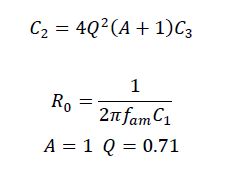
order Butterworth low pass filter to filter high frequency signals. We filter the carrier so that the cutoff frequency is 100Hz.For easy calculation, set R 5 =R 6

So, after determining R5 and R6, we get C2=220nF and C3=110nF.
Output in OUT6:
time variation

Compared with the image before LPF, it is obviously smoother. Prove that the filter filters a part of the frequency.
FFT

Judging from the final result, in the end there is almost only 100Hz frequen
cy, which is AM.
Explain why AM modulation and synchronous detection principle could be useful when you want to amp lify sig nal in low frequency drown into 1/f noise?
When using the synchronous detection method to demodulate AM signals, since the demodulation process can be regarded as the demodulation of useful signals and noise separately, there is always a separate usefu l s ignal at the output end of the demodulator, so there is no threshold effect (the useful signal is regarded as noise) in the synchronous detector. So when the op amp amplifies the signal, there is 1/ f noise, which is also amplified.
这篇关于信号处理(一)Synchronous detection同步检波(FFT,HPF,AM,FM)的文章就介绍到这儿,希望我们推荐的文章对编程师们有所帮助!


