本文主要是介绍电路Circuit- Chapter 7 First-Order Circuits(一阶电路),希望对大家解决编程问题提供一定的参考价值,需要的开发者们随着小编来一起学习吧!
First-Order Circuits
- 7.1 Introduction
- RC circuits(动态电路及其阶数)
- RL circuits
- 总结
- 例题
- 7.2 The Source-Free(无源) RC Circuit(RC电路的零输入响应)
- 7.3 The Source-Free RL Circuit(RL电路的无源响应)
- 7.4 Singularity Functions
- unit step functions
- unit impulse functions
- unit ramp functions
- 7.5 Step Response(阶跃) of RC Circuit
- Step response
- Forced response (Zero-state response)
- 7.6 Step Response of RL Circuit
- 7.7 Complete Response
- 1. Decomposition of complete response (全响应的分解)
- 2.Determining response with 3 items(三要素法)
- Applications
- 1.Delay Circuits
- 2.Photoflash Unit
- 3.Relay Circuits
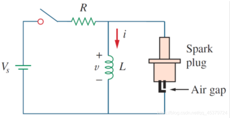
- 4.Automobile Ignition Circuit
- 总结
7.1 Introduction
Two types of simple circuits:a circuit comprising a resistor and capactior and a circuit comprising a resistor and an inductor.
These are called RC and RL circuits,respectively.
Resistive circuits


注释:损变


RC circuits(动态电路及其阶数)
动态电路:含有动态元件(电容或电感)的电路
特征:当电路的结构或参数改变时,电路可能从一种工作状态转变到另一种工作状态
换路:电路的结构或参数改变

Before switching k,circuit has reached steady state:
i = 0 , u c = 0 i=0,u_c=0 i=0,uc=0

Since k has been closed for a long time,the capacitor voltage has reached steady state again:
i = 0 , u c = U s i=0,u_c=U_s i=0,uc=Us
过渡过程:电路由一个稳态过渡到另一个稳态的过程
过渡状态(瞬态,暂态,动态)
过渡过程产生原因:电路内部含有储能元件 ,电路在换时能量 电路在换时能量 电路在换时能量 发生变化,而能量的储存和释放都需要时间

研究过渡过程具有实际意义
利用:产生各种波形
提防:暂态过程瞬间可能出现高电压,大电流,使仪器设备损坏
动态电路的阶数
描述动态电路的方程是微分方程
方程阶数=电路阶数
一阶电路:描述电路的方程是一阶微分方程,一阶电路中一般只有一个动态元件
二阶电路:描述电路的方程是二阶微分方程,一般有二个动态元件
;
应 用 K V L : R i + u c = u s 电 容 V C R : i = C d u c d t R C d u c d t + u c = u s 一 阶 微 分 方 程 也 即 一 阶 电 路 方 程 的 阶 数 通 常 等 于 电 路 中 动 态 元 件 的 个 数 应用KVL:Ri+u_c=u_s\\ 电容VCR:i=C\frac{du_c}{dt}\\ RC\frac{du_c}{dt}+u_c=u_s\\ 一阶微分方程也即一阶电路\\ 方程的阶数通常等于电路中动态元件的个数 应用KVL:Ri+uc=us电容VCR:i=CdtducRCdtduc+uc=us一阶微分方程也即一阶电路方程的阶数通常等于电路中动态元件的个数

R ( C 1 + C 2 ) d u c d t + u c = u s R(C_1+C_2)\frac{du_c}{dt}+u_c=u_s R(C1+C2)dtduc+uc=us
一阶电路
动态电路分析方法:
- 时域分析法
经典法:直接求解常微分方程
状态变量法
数值法 - 变换法
傅里叶变换法:频域分析法
拉普拉斯变换法:复频域分析法
RL circuits
Before switching k,circuit has reached steady state:
i = 0 , u L = 0 i=0,u_L=0 i=0,uL=0

Since k has been closed for a long time,the capacitor voltage has reached steady state again
u L = 0 , i = U s R u_L=0,i=\frac{U_s}{R} uL=0,i=RUs


Applying Kirchhoff’s laws to purely resistive circuits results in algebraic equations
While applying Kirchhoff’s laws to RC and RL circuits produces differential equations(微分方程)
The differential equations resulting from analyzing RC and RL circuits are of the first order.Hence.the circuits are collectively known as first-order circuits.
A first-order circuit is characterized by a first-order differential equation.
RC circuits

Applying KVL:
R i + u c = u s ( t ) Ri+u_c=u_s(t) Ri+uc=us(t)
By definition(定义)(VCR):
i = C d u c d t → R C d u c d t + u c = u s ( t ) → R d i d t + i C = d u s ( t ) d t i=C\frac{du_c}{dt}\\ ~\\ →RC\frac{du_c}{dt}+u_c=u_s(t)\\ ~\\ →R\frac{di}{dt}+\frac{i}{C}=\frac{du_s(t)}{dt} i=Cdtduc →RCdtduc+uc=us(t) →Rdtdi+Ci=dtdus(t)
RL circuits

Applying KVL:
R i + u L = u s ( t ) Ri+u_L=u_s(t) Ri+uL=us(t)
By definition(定义)(VCR):
u L = L d i d t → R i + L d i d t = u s ( t ) → R L u l + d u L d t = d u s ( t ) d t u_L=L\frac{di}{dt}\\ ~\\ →Ri+L\frac{di}{dt}=u_s(t)\\ ~\\ →\frac{R}{L}u_l+\frac{du_L}{dt}=\frac{du_s(t)}{dt} uL=Ldtdi →Ri+Ldtdi=us(t) →LRul+dtduL=dtdus(t)
Initial Conditions(初状态)
Assuming that the switching takes place at time t0

初始条件的选择,0-的时候应该达到稳态,即0处应该连续.
RC circuits

注释:电荷守恒.
RL circuits

注释:磁通守恒.
由于电阻的电压电流可以跃变,电容不可以.
总结


例题

先换路定律 u c 0 + 或 l 0 + ( u c 0 + = u v ) ) u_c0+或l_0+(u_c0+=uv)) uc0+或l0+(uc0+=uv))

换路定律
Steps to Determine Initial Conditions:
- 0-:uc(0-),iL(0-)
RC:
Substitude the capacitor with an open circuit
RL:
Substitude the inductor with a short circuit - { u c ( 0 + ) = u c ( 0 − ) i L ( 0 + ) = i L ( 0 − ) \begin{cases} u_c(0_+)=u_c(0_-)\\ i_L(0_+)=i_L(0_-) \end{cases} {uc(0+)=uc(0−)iL(0+)=iL(0−)
- 0+
RC:
Substitude the capacitor with a voltage source
RL:
Subtitude the inductor with a current source
Direction of the source!
动态电路的换路定律
- 换路:电路结构或状态发生变化
换路在t=0或t=t0时刻进行 - 换路定律


换路定律总结
当电容电流为有限值时,电容电压不跃变
当电感电压为有限值时,电感电流不跃变


7.2 The Source-Free(无源) RC Circuit(RC电路的零输入响应)
Response
A circuit response is the manner in which the circuit reacts to an excitation.
Two ways to excite the first-order circuits:
by independent sources
by initial conditions of the storage elements in the circuits(so-called source-free circuits(无源电路))
Source-free circuits
Source-free circuits are by definition free of independent sources.
Energy is initially stored in the capacitive or inductive element.
The circuits is excited by initial conditions of the storage elements in the circuits.
Natural(Zero-input) response
The natural response of a circuit refers to the behavior (in terms of voltages and currents) of the circuit itself,with no external sources of excitation.
零输入响应:
输入(激励,独立电源)为0,仅由储能元件的初始储能引起的响应


Source-Free RC Circuit

{ − u R + u C = 0 u R = R i → R C d u c d t + u c = 0 i = − C d u c d t u c = A e p t = A e − 1 R C t \begin{cases} -u_R+u_C=0\\ u_R=Ri~~~~~~~~~~~~→RC\frac{du_c}{dt}+u_c=0\\ i=-C\frac{du_c}{dt} \end{cases}\\ u_c=Ae^{pt}=Ae^{-\frac{1}{RC}t} ⎩⎪⎨⎪⎧−uR+uC=0uR=Ri →RCdtduc+uc=0i=−Cdtducuc=Aept=Ae−RC1t
Initial conditions:
u C ( 0 + ) = u C ( 0 − ) = U 0 → A = U 0 u C = U 0 e − t R C t ≥ 0 i = − C d u C d t = − C U 0 e − t R C ( − 1 R C ) = U 0 R e − t R C t ≥ 0 o r i = u C R = U 0 R e − t R C = I 0 e − t R C t ≥ 0 u_C(0_+)=u_C(0_-)=U_0→A=U_0\\ u_C=U_0e^{-\frac{t}{RC}}~t≥0\\ i=-C\frac{du_C}{dt}=-CU_0e^{-\frac{t}{RC}}(-\frac{1}{RC})=\frac{U_0}{R}e^{-\frac{t}{RC}}~t≥0\\ or\\ i=\frac{u_C}{R}=\frac{U_0}{R}e^{-\frac{t}{RC}}=I_0e^{-\frac{t}{RC}}~t≥0 uC(0+)=uC(0−)=U0→A=U0uC=U0e−RCt t≥0i=−CdtduC=−CU0e−RCt(−RC1)=RU0e−RCt t≥0ori=RuC=RU0e−RCt=I0e−RCt t≥0
总结
u c = U 0 e − t R C = U 0 e − t τ t ≥ 0 i = I 0 e − t R C = I 0 e − t τ t ≥ 0 u_c=U_0e^{-\frac{t}{RC}}=U_0e{-\frac{t}{τ}}~~t≥0\\ i=I_0e^{-\frac{t}{RC}}=I_0e^{-\frac{t}{τ}}~~t≥0 uc=U0e−RCt=U0e−τt t≥0i=I0e−RCt=I0e−τt t≥0
Note
- Voltage response of the RC circuit is an exponential decay of the initial voltage.
Current response of the RC circuit is the same exponential decay of the initial current. - The energy absorbed by the resistor up to time ∞:
W R = ∫ 0 ∞ i 2 R d t = ∫ 0 ∞ ( U 0 R e − t R C ) 2 = U 0 2 R ∫ 0 ∞ e − 2 t R C = U 0 2 R ( − R C 2 e − 2 t R C ) ∣ 0 ∞ = 1 2 C U 0 2 \large W_R=∫_0^∞ i^2 Rdt=∫_0^∞ (\frac{U_0}{R}e^{-\frac{t}{RC}})^2=\frac{U_0^2}{R}∫_0^∞ e^{-\frac{2t}{RC}}=\frac{U_0^2}{R}(-\frac{RC}{2}e^{-\frac{2t}{RC}})|_0^∞=\frac{1}{2}CU_0^2 WR=∫0∞i2Rdt=∫0∞(RU0e−RCt)2=RU02∫0∞e−RC2t=RU02(−2RCe−RC2t)∣0∞=21CU02 - a: τ τ τ:is the time required for the response to decay to a factor of 1 e \frac{1}{e} e1 or 36.8 percent of its initial value
τ = R C τ=RC τ=RC
the smaller the τ,the faster the response
u c ( t + τ ) = u c ( t ) e = 0.368 u c ( t ) i ( t + τ ) = i ( t e = 0.368 i ( t ) 3 τ → 5 τ → f i n a l s t a t e o r s t e a t y s t a t e ( f u l l y d i s c h a r g e d o r c h a r g e d ) u_c(t+τ)=\frac{u_c(t)}{e}=0.368u_c(t)\\ i(t+τ)=\frac{i(t}{e}=0.368i(t)\\ 3τ→5τ→final state or steaty state(fully discharged or charged) uc(t+τ)=euc(t)=0.368uc(t)i(t+τ)=ei(t=0.368i(t)3τ→5τ→finalstateorsteatystate(fullydischargedorcharged)
b:τ:viewed from the slope interpretation rate of t1:

7.3 The Source-Free RL Circuit(RL电路的无源响应)


7.4 Singularity Functions
Singularity functions (also called switching functions) serve as good approximations to the switching signals that arise in circuits with switching operations.
Singularity functions are functions that either are discontinuous or have discontinuous derivatives.
The three most widely used singularity functions in circuit analysis:
unit step functions
The unit step function ε(t) is 0 for negative values of t and 1 for positive values of t.
ε ( t ) = { 0 ( t < 0 ) 0 ( t > 0 ) ε(t)=\begin{cases} 0~~~(t<0)\\ 0~~~(t>0) \end{cases} ε(t)={0 (t<0)0 (t>0)


unit impulse functions
The unit impulse function δ(t) is zero everywhere except at t=0,where it is undefined.
{ δ ( t ) = 0 ( t ≠ 0 ) ∫ − ∞ ∞ δ ( t ) d t = 1 \begin{cases} δ(t)=0~~~(t≠0)\\ ∫_{-∞}^∞ δ(t)dt=1 \end{cases} {δ(t)=0 (t=0)∫−∞∞δ(t)dt=1

Integrating(积分) the unit impulse function result in the unit step function
∫ − ∞ t δ ( t ) d t = { 0 t < 0 − 1 t > 0 + = ε ( t ) ∫_{-∞}^tδ(t)dt= \begin{cases} 0~~~t<0_-\\ 1~~~t>0_+ \end{cases} =ε(t) ∫−∞tδ(t)dt={0 t<0−1 t>0+=ε(t)
The derivative(微分) of the unit step function is the unit impulse function.
d ε ( t ) d t = δ ( t ) \frac{dε(t)}{dt}=δ(t) dtdε(t)=δ(t)
unit ramp functions
Highly useful property of θ impulse function known as the sampling or shifting preperty.
∫ ∞ ∞ f ( t ) δ ( t ) d t = f ( 0 ) ∫ ∞ ∞ δ ( t ) d t = f ( 0 ) ∫_{∞}^{∞}f(t)δ(t)dt=f(0)∫_{∞}^{∞}δ(t)dt=f(0) ∫∞∞f(t)δ(t)dt=f(0)∫∞∞δ(t)dt=f(0)

∫ ∞ ∞ f ( t ) δ ( t − t 0 ) d t = f ( t 0 ) ∫_{∞}^{∞}f(t)δ(t-t_0)dt=f(t_0) ∫∞∞f(t)δ(t−t0)dt=f(t0)
7.5 Step Response(阶跃) of RC Circuit
Step response
The step response of a circuit is its behavior when the excitation is the step function,which may be a voltage or a current source.
Forced response (Zero-state response)
零状态响应:储能元件的初始储能为0,响应全部由外加激励引起


The response of the circuits due to asudden application of an independent dc voltage or current source,assuming no energy is initially stored in the capacitive or inductive element.
It is produced by the circuit when an external “force” is applied.
It represents what the circuit is forced to do by the input excitation.
The transient response is temporary ;it is the portion of the response that decays to zero as time approaches infinity.Thus,
The transient response is the circuit’s temporary response that will die out with time.
The steady-state response is the portion of the response that remains after the transient response has died out.Thus,
The steady-state response is the behavior of the circuit a long time after an external excitation is applied.
7.6 Step Response of RL Circuit


7.7 Complete Response
Complete response (or total response)
Response of circuits due to a sudden application of an independent dc voltage or current source ,assuming the energy is initially stored in the capacitive or inductive element.
全响应:非零初始状态的电路受到外加激励引起的响应
初始状态和输入共同作用


1. Decomposition of complete response (全响应的分解)


It is evident that the complete response has two components.
Classically there are two ways of decomposing this into two components.
The first is to break it into a “natural response” and a “forced response”.
The second is to break it into a “transient response” and a “steady-state response”.
u c = u c ′ + u c ′ ′ = U S + ( U 0 − U S ) e − t τ t ≥ 0 u_c=u'_c+u''_c=U_S+(U_0-U_S)e^{-\frac{t}{τ}}~~~t≥0 uc=uc′+uc′′=US+(U0−US)e−τt t≥0


2.Determining response with 3 items(三要素法)
Differential equation of first-order circuits:
α d f d t + b f = c α\frac{df}{dt}+bf=c αdtdf+bf=c
DC:
→ f ( t ) = f ( ∞ ) + [ f ( 0 + ) − f ( ∞ ) ] ⏞ A e − t τ →f(t)=f(∞)+\overbrace {[f(0_+)-f(∞)]}^A e^{-\frac{t}{τ}} →f(t)=f(∞)+[f(0+)−f(∞)] Ae−τt
{ f ( ∞ ) → s t e a d y − s t a t e r e s p o n s e : t → ∞ f ( 0 + ) → i n i t i a l c o n d i t i o n : t = 0 + τ → t i m e c o n s t a n t : t = 0 + \begin{cases} f(∞)~→steady-state response:t→∞\\ f(0_+)→initial~condition:t=0_+\\ τ~~~~~~~~→time~constant:t=0_+ \end{cases} ⎩⎪⎨⎪⎧f(∞) →steady−stateresponse:t→∞f(0+)→initial condition:t=0+τ →time constant:t=0+
Once these 3 items are determined,the response are determined.
Applications
1.Delay Circuits

2.Photoflash Unit

3.Relay Circuits

4.Automobile Ignition Circuit

总结
一 阶 电 路 { 零 输 入 响 应 : f ( 0 ) e − t τ 零 状 态 响 应 : f ( ∞ ) ( 1 − e t τ ) 全 响 应 : f ( t ) = f ( ∞ ) + [ f ( 0 + ) − f ( ∞ ) ] e − t τ ( 零 输 入 响 应 + 零 状 态 响 应 ) f ( t ) = f ′ ( t ) + [ f ( 0 + ) − f ′ ( 0 + ) ] e − t τ 正 弦 电 源 激 励 下 一阶电路\begin{cases} 零输入响应:f(0)e^{-\frac{t}{τ}}\\ 零状态响应:f(∞)(1-e^{\frac{t}{τ}})\\ 全响应:f(t)=f(∞)+[f(0_+)-f(∞)]e^{-\frac{t}{τ}}~~(零输入响应+零状态响应)\\ f(t)=f'(t)+[f(0_+)-f'(0_+)]e^{-\frac{t}{τ}} 正弦电源激励下 \end{cases} 一阶电路⎩⎪⎪⎪⎨⎪⎪⎪⎧零输入响应:f(0)e−τt零状态响应:f(∞)(1−eτt)全响应:f(t)=f(∞)+[f(0+)−f(∞)]e−τt (零输入响应+零状态响应)f(t)=f′(t)+[f(0+)−f′(0+)]e−τt正弦电源激励下
全 响 应 = { f ( t ) = f ( ∞ ) + [ f ( 0 + ) − f ( ∞ ) ] e − t τ ( 零 输 入 响 应 ) + ( 零 状 态 响 应 ) f ( ∞ ) + ( f ( 0 − ) − f ( ∞ ) ) e − t τ ( 强 制 分 量 ) + ( 自 由 分 量 ) ( 稳 态 分 量 ) + ( 瞬 态 分 量 ) 全响应= \begin{cases} f(t)=f(∞)+[f(0_+)-f(∞)]e^{-\frac{t}{τ}}(零输入响应)+(零状态响应)\\ f(∞)+(f(0_-)-f(∞))e^{-\frac{t}{τ}}(强制分量)+(自由分量)\\ (稳态分量)+(瞬态分量) \end{cases} 全响应=⎩⎪⎨⎪⎧f(t)=f(∞)+[f(0+)−f(∞)]e−τt(零输入响应)+(零状态响应)f(∞)+(f(0−)−f(∞))e−τt(强制分量)+(自由分量)(稳态分量)+(瞬态分量)
这篇关于电路Circuit- Chapter 7 First-Order Circuits(一阶电路)的文章就介绍到这儿,希望我们推荐的文章对编程师们有所帮助!


