hdlbits专题
HDLbits 刷题 -- Exams/m2014 q3
Consider the function f shown in the Karnaugh map below. Implement this function. d is don't-care, which means you may choose to output whatever value is convenient. 译:考虑下面卡诺图中显示的函数f。 实现这个函数。D是
![[HDLBits] Simple wire](/front/images/it_default.gif)
[HDLBits] Simple wire
Create a module with one input and one output that behaves like a wire. module top_module( input in, output out );assign out = in; endmodule
![[HDLBits] AND gate](/front/images/it_default.jpg)
[HDLBits] AND gate
Create a module that implements an AND gate. module top_module( input a, input b, output out );assign out=a&&b;endmodule

HDLbits 刷题 --Exams/m2014 q4i
Implement the following circuit: 实现以下电路: module top_module (output out);assign out = 1'b0;endmodule 运行结果:

HDLbits 刷题 --Always casez
学习: Build a priority encoder for 8-bit inputs. Given an 8-bit vector, the output should report the first (least significant) bit in the vector that is 1. Report zero if the input vector has no bits t
HDLbits 刷题 -- Alwaysblock2
学习: For hardware synthesis, there are two types of always blocks that are relevant: Combinational: always @(*)Clocked: always @(posedge clk) Clocked always blocks create a blob of combinational log
HDLBits——Vectors
HDLBits —— Vectors Vectors(向量;总线) 要求: 构造一个电路,拥有 1 个 3 bit 位宽的输入端口,4 个输出端口。其中一个输出端口直接输出输入的向量,剩下 3 个输出端口分别各自输出 3 bit 中的 1 bit。上图中,箭头上的小斜杠旁边的数字代表该向量(总线)的位宽,用于将向量同 wire 信号区别开来。 Solution: module top
HDLBits刷题Day24,3.2.5.9 Design a Moore FSM
3.2.5.9 Design a Moore FSM 问题描述 分析: 1.s=000时,打开fr1,fr2,fr3和补充水dfr 2.s=001时,打开fr1,fr2 3.s=011时,打开fr1 4.s=111时,关闭 5.当水位下降时,打开dfr 绘制一下状态转移图 代码: module top_module (input clk,input reset,input
「HDLBits题解」Basic Gates
本专栏的目的是分享可以通过HDLBits仿真的Verilog代码 以提供参考 各位可同时参考我的代码和官方题解代码 或许会有所收益 题目链接:Exams/m2014 q4h - HDLBits module top_module (input in,output out);assign out = in ;endmodule 题目链接:Exams/m2014 q4i - H
「HDLBits题解」Build a circuit from a simulation waveform
本专栏的目的是分享可以通过HDLBits仿真的Verilog代码 以提供参考 各位可同时参考我的代码和官方题解代码 或许会有所收益 题目链接:Sim/circuit1 - HDLBits module top_module (input a,input b,output q );//assign q = a & b ; // Fix meendmodule 题目链接:Sim/

「HDLBits题解」Building Larger Circuits
本专栏的目的是分享可以通过HDLBits仿真的Verilog代码 以提供参考 各位可同时参考我的代码和官方题解代码 或许会有所收益 题目链接:Exams/review2015 count1k - HDLBits module top_module (input clk,input reset,output [9:0] q);always @(posedge clk) beginif
HDLBits 练习 Mux256to1v
Mux256to1v 题目要求: Create a 4-bit wide, 256-to-1 multiplexer. The 256 4-bit inputs are all packed into a single 1024-bit input vector. sel=0 should select bits in[3:0], sel=1 selects bits in[7:4], sel=
「HDLBits题解」Latches and Flip-Flops
本专栏的目的是分享可以通过HDLBits仿真的Verilog代码 以提供参考 各位可同时参考我的代码和官方题解代码 或许会有所收益 题目链接:Dff - HDLBits module top_module (input clk, // Clocks are used in sequential circuitsinput d,output reg q );//// Use a
「HDLBits题解」Counters
本专栏的目的是分享可以通过HDLBits仿真的Verilog代码 以提供参考 各位可同时参考我的代码和官方题解代码 或许会有所收益 题目链接:Count15 - HDLBits module top_module (input clk,input reset, // Synchronous active-high resetoutput [3:0] q); always

Verilog练习:HDLBits笔记10
三、Circuits Combinational logic-Karnaugh Map to Circuit 1、3-variable Problem Statement: mplement the circuit described by the Karnaugh map below. module top_module(input a,input b,input c,outpu
「HDLBits题解」Bcdadd100
本专栏的目的是分享可以通过HDLBits仿真的Verilog代码 以提供参考 各位可同时参考我的代码和官方题解代码 或许会有所收益 题目链接:Bcdadd100 - HDLBits module top_module( input [399:0] a, b,input cin,output cout,output [399:0] sum ); wire [99:0] t ;genvar
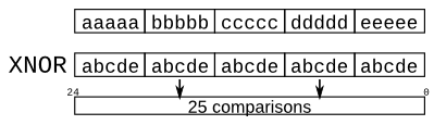
「HDLBits题解」Popcount255
本专栏的目的是分享可以通过HDLBits仿真的Verilog代码 以提供参考 各位可同时参考我的代码和官方题解代码 或许会有所收益 题目链接:Popcount255 - HDLBits module top_module( input [254:0] in,output reg [7:0] out );integer i ; always @(*) beginout = 0 ;for
「HDLBits题解」Conditional
本专栏的目的是分享可以通过HDLBits仿真的Verilog代码 以提供参考 各位可同时参考我的代码和官方题解代码 或许会有所收益 题目链接:Conditional - HDLBits module top_module (input [7:0] a, b, c, d,output [7:0] min);//// assign intermediate_result1 = compare
「HDLBits题解」Module add
本专栏的目的是分享可以通过HDLBits仿真的Verilog代码 以提供参考 各位可同时参考我的代码和官方题解代码 或许会有所收益 题目链接:Module add - HDLBits module top_module(input [31:0] a,input [31:0] b,output [31:0] sum);wire cout_u1, cout_u2 ; wire [15:0]
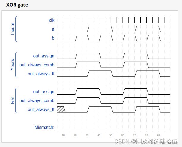
「HDLBits题解」Alwaysblock1
本专栏的目的是分享可以通过HDLBits仿真的Verilog代码 以提供参考 各位可同时参考我的代码和官方题解代码 或许会有所收益 题目链接:Alwaysblock1 - HDLBits / synthesis verilog_input_version verilog_2001module top_module(input a, input b,output wire out_ass
「HDLBits题解」Andgate
本专栏的目的是分享可以通过HDLBits仿真的Verilog代码 以提供参考 各位可同时参考我的代码和官方题解代码 或许会有所收益 题目链接:Andgate - HDLBits module top_module( input a, input b, output out );assign out = a & b ; endmodule
「HDLBits题解」Wire decl
本专栏的目的是分享可以通过HDLBits仿真的Verilog代码 以提供参考 各位可同时参考我的代码和官方题解代码 或许会有所收益 题目链接:Wire decl - HDLBits `default_nettype nonemodule top_module(input a,input b,input c,input d,output out,output out_n ); wir
hdlbits系列verilog解答(mt2015_q4)-54
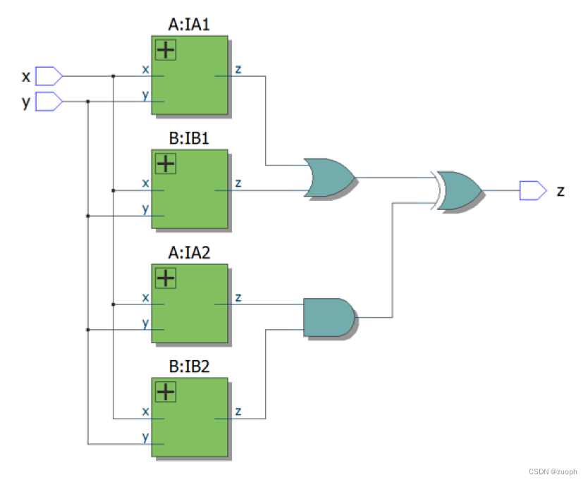
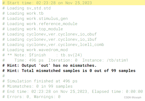
文章目录 一、问题描述二、verilog源码三、仿真结果 一、问题描述 本次使用系列文章52和53中实现的子模块,实现以下组合逻辑电路。 二、verilog源码 module top_module (input x, input y, output z);wire [3:0
hdlbits系列verilog解答(mt2015_eq2)-51
文章目录 一、问题描述二、verilog源码三、仿真结果 一、问题描述 本次要求我们创建一个电路实现对两个2位宽度的信号进行比较,如果相等输出1,不等则输出0。 模块声明 module top_module ( input [1:0] A, input [1:0] B, output z ); 二、verilog源码 module top_module ( inp
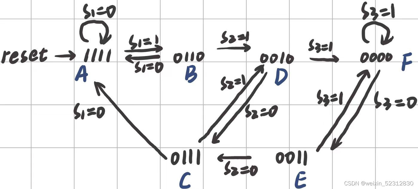
Exams/2014 q3fsm_HDLbits详解(merely状态机典型例题)
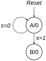
merely状态机例题 1、Consider a finite state machine with inputs s and w. Assume that the FSM begins in a reset state called A, as depicted below. The FSM remains in state A as long as s = 0, and it moves t
hdlbits系列verilog解答(exams/m2014_q4f)-47
文章目录 一、问题描述二、verilog源码三、仿真结果 一、问题描述 实现以下电路: 二、verilog源码 module top_module (input in1,input in2,output out);assign out = in1 & (~in2);endmodule 三、仿真结果 转载请注明出处!