本文主要是介绍Real-Time Rendering——9.2 The Camera照相机,希望对大家解决编程问题提供一定的参考价值,需要的开发者们随着小编来一起学习吧!
As mentioned in Section 8.1.1, in rendering we compute the radiance from the shaded surface point to the camera position. This simulates a simplified model of an imaging system such as a film camera, digital camera, or human eye.
如8.1.1节所述,在渲染中,我们计算从阴影表面点到摄像机位置的辐射。这模拟了成像系统的简化模型,如胶片相机、数码相机或人眼。
Such systems contain a sensor surface composed of many discrete small sensors. Examples include rods and cones in the eye, photodiodes in a digital camera, or dye particles in film. Each of these sensors detects the irradiance value over its surface and produces a color signal. Irradiance sensors themselves cannot produce an image,since they average light rays from all incoming directions. For this reason, a full imaging system includes a light-proof enclosure with a single small aperture (opening) that restricts the directions from which light can enter and strike the sensors. A lens placed at the aperture focuses the light so that each sensor receives light from only a small set of incoming directions. The enclosure, aperture, and lens have the combined effect of causing the sensors to be directionally specific. They average light over a small area and a small set of incoming directions. Rather than measuring average irradiance—which as we have seen in Section 8.1.1 quantifies the surface density of light flow from all directions—these sensors measure average radiance, which quantifies the brightness and color of a single ray of light.
这种系统包含由许多分立的小传感器组成的传感器表面。例子包括眼睛中的视杆细胞和视锥细胞,数码相机中的光电二极管,或者胶片中的染料颗粒。这些传感器中的每一个都检测其表面上的辐照度值,并产生颜色信号。辐照度传感器本身不能产生图像,因为它们平均来自所有入射方向的光线。由于这个原因,完整的成像系统包括具有单个小孔(开口)的不透光外壳,该小孔限制光可以进入和撞击传感器的方向。放置在孔处的透镜聚焦光,使得每个传感器仅接收来自一小组入射方向的光。外壳、光圈和透镜具有使传感器具有方向特异性的综合效果。它们将光线平均分布在一个小区域和一小组入射方向上。我们在第8.1.1节中已经看到,平均辐照度量化了来自所有方向的光流的表面密度,而这些传感器测量的是平均辐射度,它量化了单条光线的亮度和颜色。
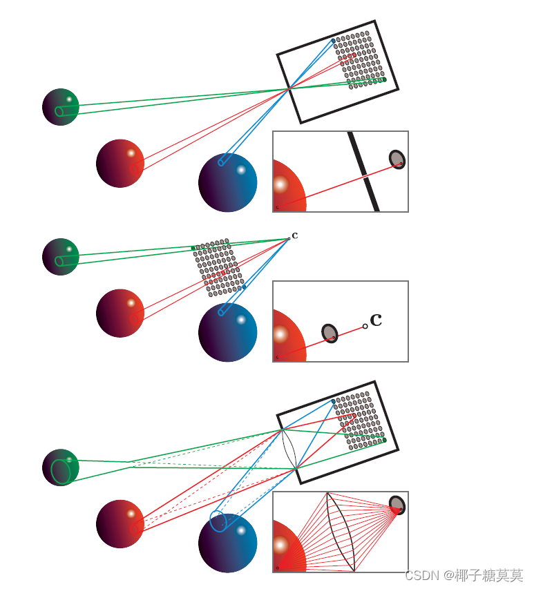
Historically, rendering has simulated an especially simple imaging sensor called a pinhole camera, shown in the top part of Figure 9.16. A pinhole camera has an extremely small aperture—in the ideal case, a zero-size mathematical point—and no lens. The point aperture restricts each point on the sensor surface to collect a single ray of light, with a discrete sensor collecting a narrow cone of light rays with its base covering the sensor surface and its apex at the aperture. Rendering systems model pinhole cameras in a slightly different (but equivalent) way, shown in the middle part of Figure 9.16. The location of the pinhole aperture is represented by the point c,often referred to as the “camera position” or “eye position.” This point is also the center of projection for the perspective transform (Section 4.7.2).
历史上,渲染模拟了一个特别简单的成像传感器,叫做针孔摄像机,如图9.16的上半部分所示。针孔相机有一个非常小的光圈——在理想情况下,一个零大小的数学点——并且没有镜头。点孔径限制传感器表面上的每个点收集单条光线,而分立的传感器收集窄锥形光线,其底部覆盖传感器表面,其顶点在孔径处。渲染系统以一种稍微不同(但等效)的方式模拟针孔摄像机,如图9.16的中间部分所示。针孔光圈的位置由点c表示,通常称为“相机位置”或“眼睛位置”该点也是透视变换的投影中心(第4.7.2节)。

Figure 9.16. Each of these camera model figures contains an array of pixel sensors. The solid lines bound the set of light rays collected from the scene by three of these sensors. The inset images in each figure show the light rays collected by a single point sample on a pixel sensor. The top figure shows a pinhole camera, the middle figure shows a typical rendering system model of the same pinhole camera with the camera point c, and the bottom figure shows a more physically correct camera with a lens. The red sphere is in focus, and the other two spheres are out of focus.
图9.16。这些相机模型人物中的每一个都包含像素传感器阵列。实线界定了由其中三个传感器从场景中收集的一组光线。每个图中的插图显示了由像素传感器上的单点样本收集的光线。上图显示了一个针孔摄像机,下图显示了同一针孔摄像机的典型渲染系统模型,摄像机点为c,下图显示了一个更符合实际的带镜头的摄像机。红色球体在焦点上,另外两个球体不在焦点上。
When rendering, each shading sample corresponds to a single ray and thus to a sample point on the sensor surface. The process of antialiasing (Section 5.4) can be interpreted as reconstructing the signal collected over each discrete sensor surface.However, since rendering is not bound by the limitations of physical sensors, we can treat the process more generally, as the reconstruction of a continuous image signal from discrete samples.
渲染时,每个着色采样对应于单个射线,因此对应于传感器表面上的采样点。抗锯齿的过程(第5.4节)可以解释为重建在每个离散传感器表面上收集的信号。但是,由于渲染不受物理传感器的限制,我们可以更普遍地处理该过程,作为来自离散样本的连续图像信号的重建。
Although actual pinhole cameras have been constructed, they are poor models for most cameras used in practice, as well as for the human eye. A model of an imaging system using a lens is shown in the bottom part of Figure 9.16. Including a lens allows for the use of a larger aperture, which greatly increases the amount of light collected by the imaging system. However, it also causes the camera to have a limited depth of field (Section 12.4), blurring objects that are too near or too far.
虽然实际的针孔照相机已经被制造出来,但是对于实践中使用的大多数照相机以及人眼来说,它们是很差的模型。图9.16的底部显示了一个使用透镜的成像系统模型。包括透镜允许使用更大的光圈,这大大增加了成像系统收集的光量。然而,这也导致相机的景深有限(第12.4节),模糊了太近或太远的物体。
The lens has an additional effect aside from limiting the depth of field. Each sensor location receives a cone of light rays, even for points that are in perfect focus. The idealized model where each shading sample represents a single viewing ray can sometimes introduce mathematical singularities, numerical instabilities, or visual aliasing.Keeping the physical model in mind when we render images can help us identify and resolve such issues.
除了限制景深之外,镜头还有一个额外的作用。每个传感器位置接收一个光线锥,即使是在完美的焦点。每个着色样本代表一条视线的理想化模型有时会引入数学奇点、数值不稳定性或视觉混叠。当我们渲染图像时,记住物理模型可以帮助我们识别和解决这些问题。
这篇关于Real-Time Rendering——9.2 The Camera照相机的文章就介绍到这儿,希望我们推荐的文章对编程师们有所帮助!


