本文主要是介绍【芯片设计- RTL 数字逻辑设计入门 6 -- 带同步复位的D触发器 RTL实现及testbench 验证】,希望对大家解决编程问题提供一定的参考价值,需要的开发者们随着小编来一起学习吧!
文章目录
- 带同步复位的D触发器
- Verilog 代码
- testbench 代码
- 编译及仿真
- 问题小结
带同步复位的D触发器

同步复位 :复位只能发生在在clk信号的上升沿,若clk信号出现问题,则无法进行复位。
Verilog 代码
// timescale ins/1nsmodule flopr (input			rstn,input			clk,input[3:0]		d,output[3:0]		q
);reg [3:0]			q_out;// synchronous reset
always@(posedge clk) beginif (!rstn) beginqout <= 4'b0;endelse beginq_out <= d;end
endassign q = q_out;
testbench 代码
module test;reg			rstn;reg			clk;reg[3:0]	d;reg[3:0]	q;flopr flopr_test(.rstn(rstn),.clk(clk),.d(d),.q(q));initial begin
`ifdef DUMP_FSDB$display("Dump fsdb wave!");$fsdbDumpfile ("test. fsdb");$fsdbDumpvars;
`endifclk = 1'b0;rstn = 1'b0;#50;rstn = 1'b1;$display("Running D trigger testbench");
endalways begin#10;clk =~ clk;$display("---run time--- : d", $time);if ($time >= 1000) begin$finish;end
endinitial begin#100 d =4'b0001;#20 d = 4'b0010;#20 d = 4'b0011; #20 d = 4'b0100;#20 d = 4'b0101; #20 d = 4'b0111;#20 d = 4'b1000;#20 d = 4'b1001;#50 $finish; // here is a system task which can stop the simulation
endendmodule
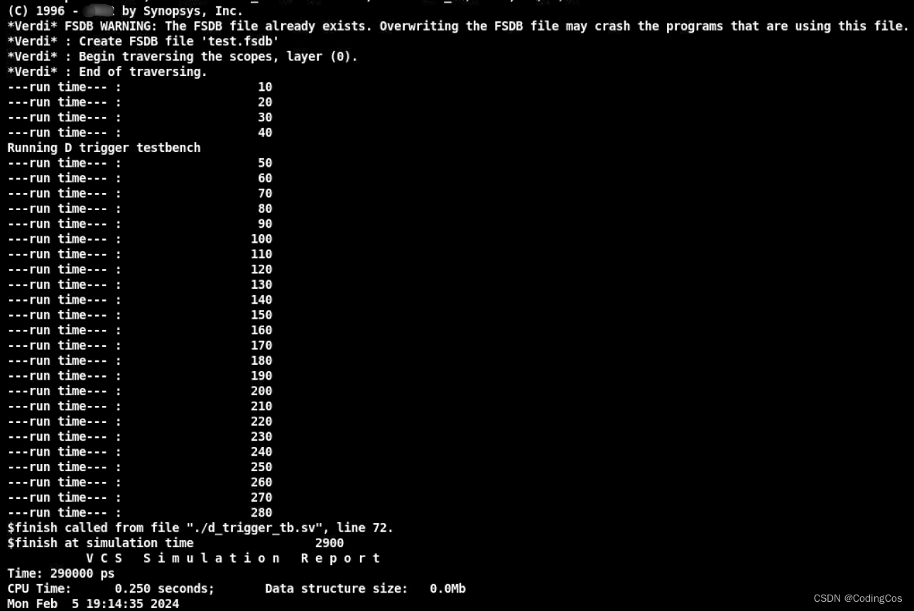
编译及仿真

波形如下:

从波形可以看到,在第100ns后,第一个 clk 时钟沿变化时 q 的信号和 d 的信号保持一样,后面依次如此。
问题小结
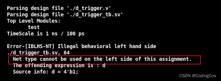
在写 testbench 测试的时候遇到了下面问题:
Net type cannot be used on the left side of this assignment.

后来发现是在 testbench 中对 q_out 的定义使用 wire 类型导致的,修改为 reg即可 。
这篇关于【芯片设计- RTL 数字逻辑设计入门 6 -- 带同步复位的D触发器 RTL实现及testbench 验证】的文章就介绍到这儿,希望我们推荐的文章对编程师们有所帮助!


