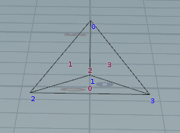
本文主要是介绍在ComponentVisualizer中画多边形,希望对大家解决编程问题提供一定的参考价值,需要的开发者们随着小编来一起学习吧!
前言
在上一篇《实践UE的ComponentVisualizer(组件可视化)的基础功能》中,ComponentVisualizer的基础功能已经实践过了,最终的效果是一个可以控制顶点的四面体线框。
作为功能的延伸,我想可以画出四面体的面,并且能选择特定面进行移动。
本来是想放在前一篇的。但仔细思考后,这一功能其实并不和ComponentVisualizer本身直接相关。因为绘制图形包括设定点击的流程,已经明确过了,即:
- 先调用
PDI->SetHitProxy,参数是新创建一个proxy。 - 使用
PDI绘制想接收点击事件的图形。 - 最后调用
PDI->SetHitProxy,参数是NULL,表明设置结束。
现在想画出面,无非是第2步中,绘制的图形由“线”、“点”变成了“多边形”。而在流程上是没有改变的。
不过画“多边形”不同于“点”和“面”,还牵扯到一些问题。所以我将这部分内容单独拿出来讨论,也表明了它并不是直接与ComponentVisualizer核心内容相关的。
讨论
FPrimitiveDrawInterface(PDI)被定义在\Runtime\Engine\Public\SceneManagement.h中:
/*** The base interface used to query a primitive for its dynamic elements.*/
class FPrimitiveDrawInterface
其中有上一篇用过的DrawLine与DrawPoint函数。
而同样在SceneManagement.h文件中的是,还有很多辅助的用来绘制图形的函数,它们将PDI作为了参数。
//
// Primitive drawing utility functions.
//// Solid shape drawing utility functions. Not really designed for speed - more for debugging.
// These utilities functions are implemented in PrimitiveDrawingUtils.cpp.
...

其中有一些是画线框,但有些传入了FMaterialRenderProxy参数,是可以画多边形的:

比如,我可以调用DrawTriangle画一个三角形面。
那现在问题就是,参数中的FMaterialRenderProxy该如何得到呢?
在编辑器中,几何体笔刷(BSP)的编辑模式的代码在GeometryEdMode中。
 而在
而在FEdModeGeometry::RenderPoly中,有MaterialRenderProxy的创建逻辑:
void FEdModeGeometry::RenderPoly( const FSceneView* View, FViewport* Viewport, FPrimitiveDrawInterface* PDI )
{for( int32 ObjectIdx = 0 ; ObjectIdx < GeomObjects.Num() ; ++ObjectIdx ){... // Allocate the material proxy and register it so it can be deleted properly once the rendering is done with it.FDynamicColoredMaterialRenderProxy* SelectedColorInstance = new FDynamicColoredMaterialRenderProxy(GEngine->GeomMaterial->GetRenderProxy(),SelectedColor );PDI->RegisterDynamicResource( SelectedColorInstance );FDynamicColoredMaterialRenderProxy* UnselectedColorInstance = new FDynamicColoredMaterialRenderProxy(GEngine->GeomMaterial->GetRenderProxy(),UnselectedColor);PDI->RegisterDynamicResource( UnselectedColorInstance );		// Render selected filled polygons.for( int32 PolyIdx = 0 ; PolyIdx < GeomObject->PolyPool.Num() ; ++PolyIdx ){...PDI->SetHitProxy( new HGeomPolyProxy(GeomPoly->GetParentObject(),PolyIdx) );{FDynamicMeshBuilder MeshBuilder(View->GetFeatureLevel());...if( GeomPoly->IsSelected() ){MeshBuilder.Draw(PDI, GeomObject->GetActualBrush()->ActorToWorld().ToMatrixWithScale(), SelectedColorInstance, SDPG_World, false );}else{// We only draw unselected polygons in the perspective viewportif( !Viewport->GetClient()->IsOrtho() ){// Unselected polygons are drawn at the world level but are bumped slightly forward to avoid z-fightingMeshBuilder.Draw(PDI, GeomObject->GetActualBrush()->ActorToWorld().ToMatrixWithScale(), UnselectedColorInstance, SDPG_World, false );}}}PDI->SetHitProxy( NULL );}}
}
代码中创建了两次,是为了选择与非选择的状态分别创建不同的材质。
而FDynamicColoredMaterialRenderProxy继承自FMaterialRenderProxy,完整继承关系如下:
FDynamicColoredMaterialRenderProxy创建简单,基本上只需要一个颜色。因此我想这就是我所需要的MaterialRenderProxy。
实现
主要的代码还是增加在DrawVisualization中:
for (int f = 0; f < 4; f++)
{//材质:FDynamicColoredMaterialRenderProxy* MaterialProxy = new FDynamicColoredMaterialRenderProxy(GEngine->GeomMaterial->GetRenderProxy(),(comp->SelectingFaceIndex == f) ? FLinearColor(0.8, 0.5, 0.0, 1.0) :FLinearColor(0, 0.3, 0.5, 1.0));//根据是否选择而决定颜色PDI->RegisterDynamicResource(MaterialProxy);//开始设置ProxyPDI->SetHitProxy(new HYaksueHitProxy(Component, -1, f));//绘制三角面DrawTriangle(PDI, comp->Points[comp->Faces[f][0]], comp->Points[comp->Faces[f][1]], comp->Points[comp->Faces[f][2]], MaterialProxy, SDPG_World);//结束设置ProxyPDI->SetHitProxy(NULL);
}
需要注意的是三角形的时针顺序,因为它会影响剔除:

Faces.Add({ 1,3,2 });
Faces.Add({ 0,1,2 });
Faces.Add({ 0,2,3 });
Faces.Add({ 0,3,1 });
另外值得一提的是,DrawTriangle只是画一个三角形,如果要画更多的面,或许要需要学它内部的方式——使用FDynamicMeshBuilder来做:
void DrawTriangle(class FPrimitiveDrawInterface* PDI, const FVector& A, const FVector& B, const FVector& C, const FMaterialRenderProxy* MaterialRenderProxy, uint8 DepthPriorityGroup)
{FVector2D UVs[4] ={FVector2D(0,0),FVector2D(0,1),FVector2D(1,1),FVector2D(1,0),};FDynamicMeshBuilder MeshBuilder(PDI->View->GetFeatureLevel());FVector Normal = FVector(0, 0, 1);FVector Tangent = FVector(1, 0, 0);	MeshBuilder.AddVertex(FDynamicMeshVertex(A, Tangent, Normal, UVs[0],FColor::White));MeshBuilder.AddVertex(FDynamicMeshVertex(B, Tangent, Normal, UVs[1], FColor::White));MeshBuilder.AddVertex(FDynamicMeshVertex(C, Tangent, Normal, UVs[2], FColor::White));MeshBuilder.AddTriangle(0, 1, 2);MeshBuilder.Draw(PDI, FMatrix::Identity, MaterialRenderProxy, DepthPriorityGroup, false, false);PDI->DrawLine(A, B, FColor::Yellow, DepthPriorityGroup, 1.f);PDI->DrawLine(A, C, FColor::Yellow, DepthPriorityGroup, 1.f);PDI->DrawLine(B, C, FColor::Yellow, DepthPriorityGroup, 1.f);
}
效果

最终代码
YaksueComponent.h:
#pragma once#include "CoreMinimal.h"
#include "UObject/ObjectMacros.h"
#include "Components/ActorComponent.h"#include "YaksueComponent.generated.h"UCLASS(meta = (BlueprintSpawnableComponent))
class UYaksueComponent : public UActorComponent
{GENERATED_UCLASS_BODY()public:TArray<FVector> Points;		//点的位置int32 SelectingPointIndex;	//正在选择的点序号TArray<TArray<int>> Faces;	//面所包含的点序号,如果不是选择点则应为-1int32 SelectingFaceIndex;	//正在选择的面序号,如果不是选择面则应为-1//获得所有所选的点TArray<int> GetSelectingPoints() const;
};
YaksueComponent.cpp:
#include"YaksueComponent.h"UYaksueComponent::UYaksueComponent(const FObjectInitializer & ObjectInitializer): Super(ObjectInitializer)
{//四个顶点位置:Points.Add(FVector(0, 0, 100));Points.Add(FVector(100, 0, 0));Points.Add(FVector(-50, -86, 0));Points.Add(FVector(-50, 86, 0));SelectingPointIndex = -1;	//初始化为-1表示未选择任何点//四个面的顶点序号:(注意应为逆时针)Faces.Add({ 1,3,2 });Faces.Add({ 0,1,2 });Faces.Add({ 0,2,3 });Faces.Add({ 0,3,1 });SelectingFaceIndex = -1;	//初始化为-1表示未选择任何面
}TArray<int> UYaksueComponent::GetSelectingPoints() const
{if (SelectingPointIndex >= 0)		//如果选择了点则返回当前选择点return { SelectingPointIndex };else if (SelectingFaceIndex >= 0)	//如果选择了面则返回面上所有的点return Faces[SelectingFaceIndex];elsereturn {};
}
YaksueComponentVisualizer.h:
#pragma once#include "ComponentVisualizer.h"class FYaksueComponentVisualizer : public FComponentVisualizer
{
public:class UYaksueComponent* CurrentEditingComponent;//当前正在编辑的组件,应在VisProxyHandleClick中设置。//绘制组件可视化的图形:virtual void DrawVisualization(const UActorComponent* Component, const FSceneView* View, FPrimitiveDrawInterface* PDI) override;//接收点击事件virtual bool VisProxyHandleClick(FEditorViewportClient* InViewportClient, HComponentVisProxy* VisProxy, const FViewportClick& Click) override;//指定操纵器控件的位置virtual bool GetWidgetLocation(const FEditorViewportClient* ViewportClient, FVector& OutLocation) const override;//处理操纵器控件的输入virtual bool HandleInputDelta(FEditorViewportClient* ViewportClient, FViewport* Viewport, FVector& DeltaTranslate, FRotator& DeltalRotate, FVector& DeltaScale) override;
};//收集点击信息的proxy,既针对点也针对面
struct HYaksueHitProxy : public HComponentVisProxy
{DECLARE_HIT_PROXY();HYaksueHitProxy(const UActorComponent* InComponent, int32 InPointIndex, int32 InFaceIndex);//记录哪一个点,如果不是点则应为-1int32 PointIndex;//记录哪一个面,如果不是面则应为-1int32 FaceIndex;
};
YaksueComponentVisualizer.cpp:
#include"YaksueComponentVisualizer.h"
#include"YaksueComponent.h"#include"EditorModes.h"DEFINE_LOG_CATEGORY_STATIC(LogYaksueComponentVisualizer, Log, All);
//UE_LOG(LogYaksueComponentVisualizer, Warning, TEXT("log %s"),);IMPLEMENT_HIT_PROXY(HYaksueHitProxy, HComponentVisProxy);HYaksueHitProxy::HYaksueHitProxy(const UActorComponent * InComponent, int32 InPointIndex, int32 InFaceIndex): HComponentVisProxy(InComponent,	//组件HPP_Wireframe),	//优先级PointIndex(InPointIndex),FaceIndex(InFaceIndex)
{
}void FYaksueComponentVisualizer::DrawVisualization(const UActorComponent* Component, const FSceneView* View, FPrimitiveDrawInterface* PDI)
{//将组件类型转换为UYaksueComponentconst UYaksueComponent* comp = (UYaksueComponent*)Component;//在所有顶点之间画线:for (int i = 0; i < 4; i++)for (int j = i + 1; j < 4; j++)PDI->DrawLine(comp->Points[i],			//起点comp->Points[j],			//终点FLinearColor(0, 1, 1, 1),	//颜色SDPG_Foreground);			//前景//绘制四个顶点并放置Proxyfor (int i = 0; i < 4; i++){//开始设置ProxyPDI->SetHitProxy(new HYaksueHitProxy(Component, i,-1));//画点:PDI->DrawPoint(comp->Points[i],			//位置//根据是否选择而决定颜色:(comp->SelectingPointIndex == i) ? FLinearColor(0, 1, 0, 1) : FLinearColor(1, 1, 0, 1),	20.f,						//大小SDPG_Foreground);			//前景//结束设置ProxyPDI->SetHitProxy(NULL);}//绘制四个面for (int f = 0; f < 4; f++){//材质:FDynamicColoredMaterialRenderProxy* MaterialProxy = new FDynamicColoredMaterialRenderProxy(GEngine->GeomMaterial->GetRenderProxy(),(comp->SelectingFaceIndex == f) ? FLinearColor(0.8, 0.5, 0.0, 1.0) :FLinearColor(0, 0.3, 0.5, 1.0));//根据是否选择而决定颜色PDI->RegisterDynamicResource(MaterialProxy);//开始设置ProxyPDI->SetHitProxy(new HYaksueHitProxy(Component, -1, f));//绘制三角面DrawTriangle(PDI, comp->Points[comp->Faces[f][0]], comp->Points[comp->Faces[f][1]], comp->Points[comp->Faces[f][2]], MaterialProxy, SDPG_World);//结束设置ProxyPDI->SetHitProxy(NULL);}
}bool FYaksueComponentVisualizer::VisProxyHandleClick(FEditorViewportClient* InViewportClient, HComponentVisProxy* VisProxy, const FViewportClick& Click)
{const HYaksueHitProxy* Proxy = (HYaksueHitProxy*)VisProxy;//设置当前正在编辑的组件:CurrentEditingComponent = (UYaksueComponent*)Proxy->Component.Get();//设置当前所选的点与面的序号CurrentEditingComponent->SelectingPointIndex = Proxy->PointIndex;CurrentEditingComponent->SelectingFaceIndex = Proxy->FaceIndex;//测试输出所点击的点的序号//UE_LOG(LogYaksueComponentVisualizer, Warning, TEXT("click point : %d"), Proxy->PointIndex);return true;
}bool FYaksueComponentVisualizer::GetWidgetLocation(const FEditorViewportClient* ViewportClient, FVector& OutLocation) const
{//位置就是当前所选点的平均位置:FVector amount = FVector(0, 0, 0);for (int i = 0; i < CurrentEditingComponent->GetSelectingPoints().Num(); i++)amount += CurrentEditingComponent->Points[CurrentEditingComponent->GetSelectingPoints()[i]];OutLocation = amount/ CurrentEditingComponent->GetSelectingPoints().Num();return true;
}bool FYaksueComponentVisualizer::HandleInputDelta(FEditorViewportClient* ViewportClient, FViewport* Viewport, FVector& DeltaTranslate, FRotator& DeltalRotate, FVector& DeltaScale)
{//处理位移:if (!DeltaTranslate.IsZero()){//当前所选的顶点加上位移:for (int i = 0; i < CurrentEditingComponent->GetSelectingPoints().Num(); i++)CurrentEditingComponent->Points[CurrentEditingComponent->GetSelectingPoints()[i]] += DeltaTranslate;}return true;
}
2023.2.27更新:
发现这里似乎少依赖一个模块:RenderCore
这篇关于在ComponentVisualizer中画多边形的文章就介绍到这儿,希望我们推荐的文章对编程师们有所帮助!


