本文主要是介绍MSP-EXP432实践项目 小车游戏,希望对大家解决编程问题提供一定的参考价值,需要的开发者们随着小编来一起学习吧!
一 设备
软件:Code Composer Studio (IDE from Texas Instruments)
硬件:MSP-EXP432P401R (Cortex M4F)、Educational BoosterPack MKII
二 储备知识
2.1 嵌入式系统的主要架构:
- 事件驱动
- 时间触发
2.2 嵌入式系统内核的主要组成部分:
- 微控制器
中央处理单元(CPU),主存储器和片上外设需要控制系统。市面上存在非常多的微控制器。
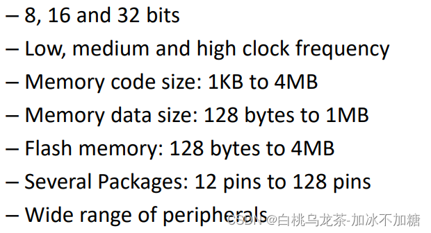
- 微处理器
- 数字信号处理器DSP
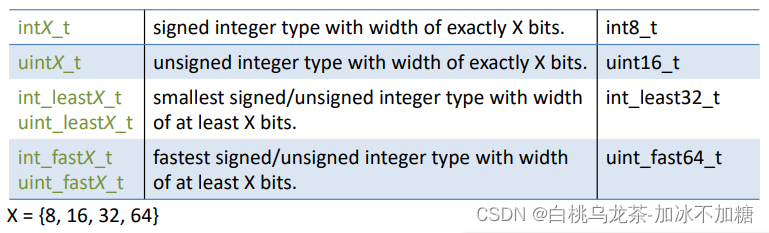
2.3 数据类型
不同编译器和不同处理器数据类型不同。<stdint.h>文件显式声明了类型大小。
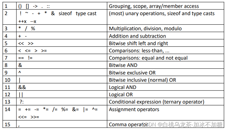
2.4 运算符优先级
多使用圆括号
2.5 关键字
typedef创建新类型typedef char str40[41]; str40 message;typedef uint16_t t_ticks; t_ticks time;typedef struct {int x, y, z;} t_coordinates; t_coordinates position; position.x = 100; position.y = 54;extern变量在其他文件中声明,允许在多个文件之间全局共享变量。
在编译时不会进行内存分配,只检查类型正确性。static用于函数时可以减少函数的作用域;用于变量时除可以减少函数作用域外,还可以保持变量。 static 声明的变量不会在每次函数调用中创建,只初始化一次,并在其他调用时维持变量的值。而变量的作用域仅限于声明变量的文件或函数(静态局部变量)。使用局部变量允许重用源代码。volatile用于防止编译器优化。
2.6 竞态
-
来源:两个能以不可预测的顺序(并发性)运行的独立代码段修改共享变量。如多线程任务间、普通代码和中断处理之间。
-
避免:
- 中断——不使用全局变量,创建函数来访问变量。访问变量时禁止中断(临界区与原子访问)。
- 并发系统——使用信号量,互斥,自旋锁。不要使用信号量或类似的中断。永远不要锁定中断服务程序。
2.7 超时
-
软件超时
unsigned int Timeout = some_value;
while(!(data_ready) && (++Timeout));
可以调整初值,但是很难设置一个特定的时间值
-
硬件超时
Set_timer_and_run (Timeout_value);
while(!(data_ready) && (!TimerFlag));
时间可以非常精确地调整,从毫秒到秒
-
最好的方法是对串行输入和定时器都使用中断。系统将受益于睡眠模式,甚至可以多任务处理。
2.8 MISRA-C
MISRA-C是C语言的一个子集,旨在改进与软件相关的安全系统
C语言的高效性也导致其实时运行错误检查工具较弱,没有try-catch。程序员需要自行进行错误检查。
偏差:一个正式的程序,涉及到整个团队甚至部门必须授权的偏差。必须有文件记录并证明是合理的。项目偏差涉及所有项目代码;特定偏差只涉及一个文件中的一个实例。
2.9 C语言扩展
- SFR(Special function register) access
//Cortex style: #define P5 ((DIO_PORT_Odd_Interruptable_Type*)(DIO_BASE+0x0040)) - 标准位定义,每个BIT均只有一位为1
#define BIT0 (0x0001u)
#define BIT1 (0x0002u)
#define BIT2 (0x0004u)
#define BIT3 (0x0008u)
……
#define BITF (0x8000u)
//为某些位清零 Var &= ~(BIT3 | BIT8 | BITD | BITF); //为某些位置一 Var |= (BIT0 | BITA | BITE); //取某些位的值 Check1 = Var & BIT0; Check2 = Var & BIT1; Check3 = Var & BIT6; //切换位/取反位:按位异或(不同为1,相同为0) aux_c ^= BIT2; - 中断服务例程(Interrupt Service Routine, ISR)。编译器提供预定义的函数名。
- CCS编译器提供了访问底层处理器指令的内在函数。内在函数编译内联的机器代码。头文件"intrinsic.h"。
三 硬件资料
3.0 简介
- Arm®32位Cortex®-M4F CPU最高可达48MHz。
- 具备浮点单元和内存保护单元;有256KB闪存和64KB的SRAM。具备超低功耗模式,片上调试器,包括数字I/O、定时器、倍增器、ADC、通信、DMA等几种片上外设。
- 其低供电电压范围从1.62V至3.7V。
3.1 SFR
通过大量的SFR(Special Function Register)管理外围设备。SFR不是一个存储数据的寄存器,是CPU与外设通信的寄存器。
- CPU写入SFR来配置和控制外设。如在模拟输出中设置电压。
- CPU读取SFR从外设获取数据或状态。如知道数字引脚是高电压还是低电压
访问方式:
-
MSP430 style (宏指令)
P5SEL0 |= 0x2A; TA0CCTL3 &= 0x27; -
CMSIS style (指针) 【更优选择】
P5->SEL0 |= 0x2A ;
TIMER_A0->CCTL[3] &= 0x27:
ADC14->MCTL[9] = 0;
3.2 振荡器和系统时钟
- 时钟来源(硬件):
- LFXT:用于 32 kHz 或以下的晶体、谐振器或外部信号的低频振荡器。
- HFXT:用于晶体,谐振器或外部信号在 1 MHz至 48 MHz 的高频振荡器。
- DCO:内部数字控制振荡器(DCO)。
- VLO:内部极低功率,9.4 KHz 频率。
- REFO:内部低功率修剪 32768 KHz 或 128 KHz。
- MODOSC:内部低功率振荡器 25 MHz。
- SYSOSC:内部 5MHz。
另:可以同时使用一个、两个或三个源。
- 时钟CPU和外设的系统时钟信号:
- MCLK:主时钟。是CPU时钟和外围设备。
- ACLK:辅助时钟。外围设备。
- HSMCLK:子系统主时钟。外围设备。
- SMCLK:低速子系统主时钟。外围设备。
- BCLK:低速备份域。
- 也可以使用原有的硬件信号。
所有这些都可以从任何硬件时钟源生成,并可以被1、2、4、8、16、32、64或128划分。
时钟源数量多的原因:低功率需要低频率;现代应用需要高频率。如果有电力限制,必须仔细设计和编程时钟系统。
3.3 操作模式
低功率并不总是意味着低功耗,低功率是指什么都不做的时候省电。现代微控制器提供多种不同性能和消耗的操作模式。应用程序决定何时进入低功耗模式,物理事件“唤醒”微控制器。
MSP432家族提供了几种低功耗操作模式(LPM)。
- 写入SFR状态寄存器(SR)进入微选择的模式(内在功能)。
- 中断从任何模式唤醒µC(需要启用)
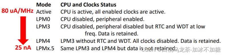
系统总是由I/O中断和RST信号唤醒。如果时钟启用,由RTC和WDT中断唤醒。
- 如果在进入LPM前忘记使能中断:
- LPM4.5和关机的区别:
当微控制器被中断唤醒时:
- 中断服务程序(ISR)必须处理操作模式。
- 它是可能离开状态,寄存器没有改变,所以微控制器返回到相同的低功耗模式。
- 可以更改状态寄存器,并选择另一种操作模式。例如,编程定时器,睡眠微控制器,唤醒因为定时器中断,改变到活动模式,并正常工作,直到有事件改到睡眠模式。
3.4 中断
中断是表示需要注意的异步信号,使处理器保存其执行状态并开始执行中断处理程序(ISR)。ISR执行后,程序正常恢复。中断可以避免在轮询循环中浪费CPU周期。
- 中断向量是ISR的内存地址。
- 在MSP432中断是CPU的一部分(Cortex M),NVIC可以为特定的微控制器量身定制。
- 来自外围设备(而非SysTick)的中断需要三个级别的启用:全局,NVIC,外围
NVIC的主要特点:
- 64个中断源,3个优先级位。值越低,优先级越高
- 嵌套。ISR可以被一个更高优先级的中断抢占。
- 可屏蔽。三个层次:全局、NVIC、外围。
- 电平和脉冲中断。中断可以有四种状态:inactive、pending、active、active and pending。这允许ISR在状态处于挂起和活动状态时重新启动。
1) 全局中断使能
- 启用所有单独启用的中断
- CPU核心寄存器中的
PRIMASK位允许/阻止中断- PRIMASK=0 启用中断
- PRIMASK=1 禁止中断
- 访问方式:
- CMSIS库函数(ARM内联函数)
void __set_PRIMASK (uint32_t priMask) // Set PRIMASK to value priMask uint32_t __get_PRIMASK (void) // Returns the value of PRIMASK void __enable_irq (void) //Clears PRIMASK to 0 void __disable_irq (void) //Sets PRIMASK to 1- 内联函数(Texas Instrument)
uint32_t _enable_interrupts (void)
// Returns previous value of PRIMASK and set it to 0
uint32_t _disable_interrupts (void)
// Returns previous value of PRIMASK and set it to 1
void _restore_interrupts (uint32_t priMask)
// Set PRIMASK to value priMask
2) NVIC中断使能
- 只启用单独启用的中断。
- 访问方式:
- CMSIS库函数(ARM内联函数)
NVIC_EnableIRQ(IRQn_Type IRQn) // IRQn is the IRQ number.- 访问NVIC寄存器
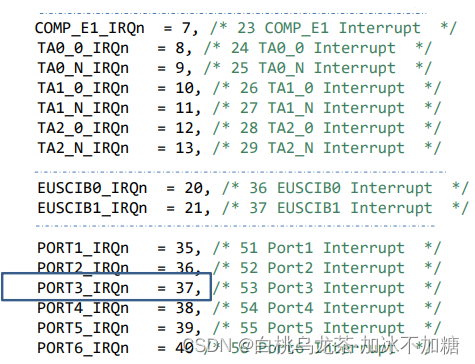
NVIC->ISER[x] |= 0x01 << (IRQn & 31); // x = 0 for IRQs 0 to 31, and x = 1 for IRQs 32 to 63. // 保留IRQn的低5位(因为超过31重新计数),将1左移对应的位数/* 举例 */ NVIC_EnableIRQ (37); NVIC_EnableIRQ (PORT3_IRQn); NVIC->ISER[1] |= 0x01 << (PORT3_IRQn & 31); - 宏定义
3) 外围中断使能
每个外设有一组寄存器(SFR)。这些寄存器中的一些位允许中断。当外设引发(触发)中断时,一个或多个位被设置为1以指示该事件。这些位称为FLAGS,存储在SFR中。
- 如果只有一个FLAG可以引发中断,清除FLAG然后反应
- 如果有多个FLAG可以引发中断,检查是哪个FLAG导致的中断,清除它然后反应
- 不要声明非静态变量。
- 不要运行花费长时间的代码。
4) 中断与竞态
在ISR和其他函数之间共享变量可能会产生严重的问题。程序将以不同的方式运行,这取决于事件的顺序或时间。
解决方案是使用**原子函数(临界区)**来检查和修改共享变量,在操作修改变量前禁用中断,在完成操作之后启用中断。
static uint8_t FLAG_X=1; //module scope
uint8_t Check_FLAG_X (){uint8_t copy;uint32_t int_state;int_state = disable_interrupts(); // 禁用中断copy = FLAG_X; // 读变量值FLAG_X = 0; // 清除变量值_restore_interrupts (int_state); // 恢复中断return (copy);
}
//主函数
... ...
while (1){... ...if (Check_FLAG_X()){DO_TASK();}... ...
}
3.5 数字IO
MSP432P401R有多达84个通用输入/输出引脚(GPIO端口或简单的I/O端口)。大多数端口为8位长度。一些端口引脚与其他外设功能是多路复用的。
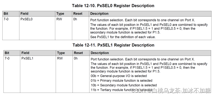
PxSEL0和PxSEL1用于选择引脚功能
PxDIR(8位大小)允许选择引脚方向

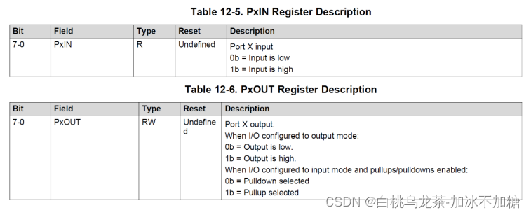
PxIN(8位大小)用于读取GPIO引脚的状态
—输入为低时,则该位值为0。
—输入为高时,则该位值为1。
PxOUT(8位大小)用于写入GPIO引脚的状态
—置为0,输出为低压。
—置为1,输出为高压。
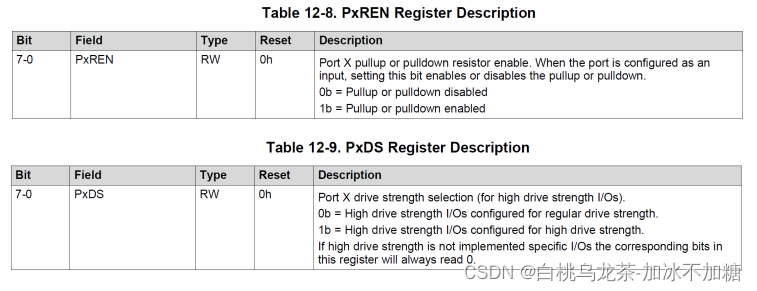
PxREN(8位大小)允许在DIR设置为INPUT时启用上拉或下拉电阻
—0:禁用上拉/下拉电阻
—1:启用上拉/下拉电阻
此时PxOUT(8位大小)用于选择上下拉电阻
—置为0,下拉。
—置为1,上拉。
PxDS(8位大小)设置驱动器强度(电流)
—设置为0位,降低驱动器强度(默认)。
—设置为1位,全驱动强度
从端口P1到端口P10的每个引脚都能产生中断(引脚状态改变时产生中断)
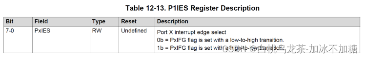
PxIES(8位大小)控制产生中断的变化
—设置为0位,选择低到高。
—设置为1位,选择高到低。
PxIE(8位大小)启用/禁用中断
—设置为0位,表示关闭中断。
—设置为1位,表示使能中断。
PxIFG(8位大小)每个引脚一个位标志
—当选中的边出现时置位为1。
—当该标志被设置时,引发中断(启用中断时)。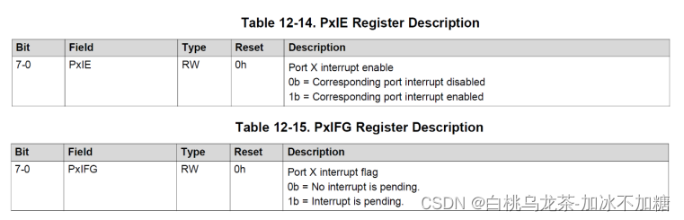
必须在中断处理程序中检查PxIFG以确认中断的来源,随后立即清除标志位。
void PORT5_IRQHandler(){if (P5->IFG & BIT0){P5->IFG &= ~BIT0; //CLEAR THE FLAG!!!!//write your code}if (P5->IFG & BIT4){P5->IFG &=~BIT4; //CLEAR THE FLAG!!!!//write your code}
}
另一种方法是使用中断向量。【更优选择】
PxIV(16位大小)表示引发中断的最高优先级引脚
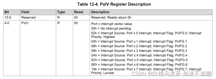
每次读取PxIV时,它的值都会更新到最高优先级的暂挂中断之后。读取PxIV时自动清除相应的PxIFG标记。
访问PxIV的方式有两种。第一种使用switch case语句,如果设置了两个标志,它将运行两次的ISR。第二种采用复制PxIV寄存器的值来确保正确地多次运行。
// 方法一
void PORT5_IRQHandler(){switch (P5->IV){case DIO_PORT_IV__IFG0://write your codebreak;case DIO_PORT_IV__IFG4://write your codebreak;default:{}break;}
}
// 方法二
void PORT5_IRQHandler(){static uint8_t copy;copy = P5->IV;if (copy & BIT0) {...}if (copy & BIT4) {...}
}
注意
- 写入PxOUT, PxDIR, PxIES或PxREN可以导致设置相应的PxIFG,也就是说,会得到一个错误的中断。解决办法是在配置端口后清除标志。
- 任何外部中断事件都应至少为20ns / 1µs。(非毛刺滤波器/毛刺滤波器)。
- 如果你不使用PxIV,必须检查PxIFG的位,并在检查之后通过软件清除它们。
- 如果你使用PxIV,你不需要检查PxIFG或清除标志,在ISR内部只读取一次PxIV。
- 机械开关在输出时需要除颤,可通过硬件或软件实现。对触发器,RC电路,除颤IC,可以使用中断;延迟,计数器,时间触发轮询则不需要中断。
3.6 高精度ADC (ADC14)
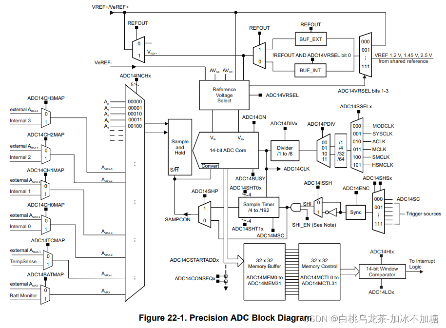
1)特点
- 多达32个模拟输入(32个单独,16个差分)。
- 内部和外部电压参考。
- 两个采样和保持模式,包含它们独自的时钟。
- 启动转换的几个来源。
- 14,12,10,8位分辨率。
- 32个存储寄存器。
- 单采集、重复采集、序列采集(4种模式)。
- 窗口比较器。
- 中断能力准备,捕获和溢出。含38个中断源。
2)参考电压与输出
数字输出:N_ADC = 16384 × [V_(in+) — V_(r-)] / [V_(r+) — V_(r-)]
-
输入模拟电压 V_in 范围:0V~AVcc
- AVcc 范围从1.62V到3.7V。
- 若 V_in 超出操作范围:
V_in ≥ V_(r+),N_ADC = 0x3FFF (Full scale)
V_in ≤ V_(r-),N_ADC = 0x0000
V_in超过[0, Vcc],会损坏ADC
-
参考正电压 Vr+ 从1.45V到AVcc。可能的来源包括:
- 从外部引脚VeRef+。
- 从内部参考电压(1.2V, 1.45或2.5V);来自AVcc(微控制器电源)
-
参考负电压 Vr- 总是0V。可能的来源包括:
- 外部引脚VeRef-(建议为0 V)。
- 来自Avss(地面)
由此可知,ADC不会输出负信号,且分辨率可调节。
3)输入源
多达32个外部输入,6个内部输入(软件可选):内部温度传感器,AVcc/2(电池监控器)和4个输入(取决于设备)。
输入是多路复用的,因此不可能同时对两个或多个输入进行采样。外部输入与几个DIO端口共享,因此必须使用PxSEL0和PxSEL1配置每个引脚。
4)时钟
采用逐次逼近转换方式,需要时钟ADC14CLK。
ADC14CLK有6个时钟源。
- MODCLK, SYSCLK, ACLK, MCLK, SMCLK, HSMCLK
- 时钟源可以被1、4、32或64分割
- 在上述基础上还可以再除以1、2、4、6、8
- 低频:高转换时间,高频:低转换时间。最大转化率为1 Msps。(不推荐)
5)采样保持及其模式
开始转换并不意味着“开始将模拟转换为数字”,而是意味着:
- 首先,输入信号必须被“采样”。
- 第二,保持它(就像“拍照”一样)。
- 第三,转换(16 ADC14CLK时钟)。分辨率越低,循环次数越少。
上述步骤由SHI的上升边启动。生成SHI的几个源包括:
- AD14SC 位 (software start)。
- 计时器的几个输出。不需要CPU干预,定期捕获输入信号;检查具体设备的数据表
外部采样模式SHP=0
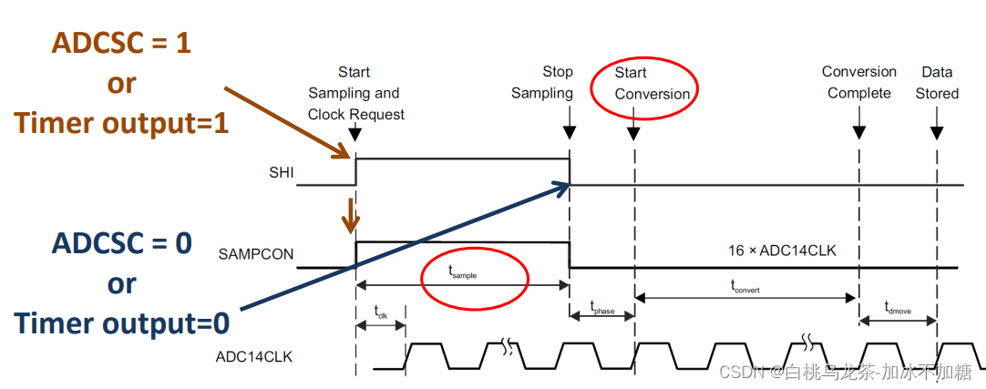
SHI行为控制采样时间
脉冲采样模式SHP=1
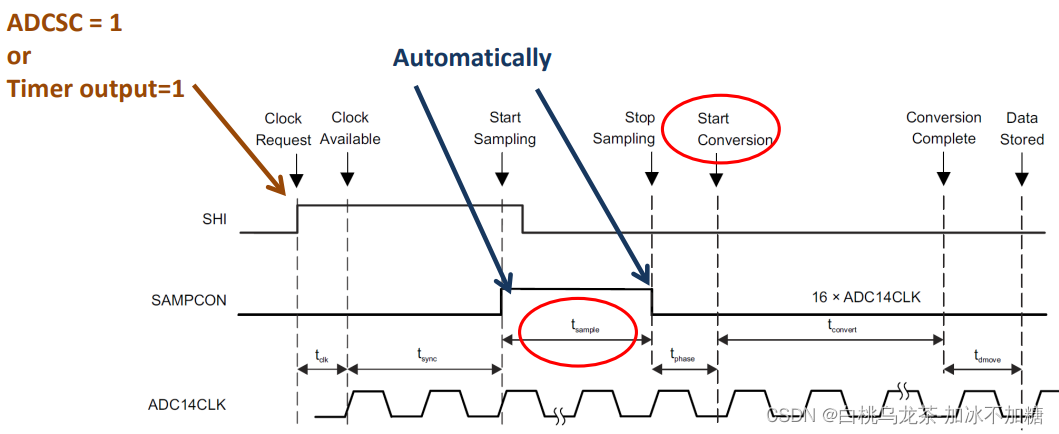
SHI触发采样,采样时间由ADC14 CTL0寄存器的ADCSHT0x和ADCSHT1x位决定。其中ADC14SHT0x适用于ADC14MCTL8到ADC14MCTL23,ADC14SHT1x用于ADC14MCTL0到ADC14MCTL7和ADC14MCTL24到ADC14MCTL31。
采样时间很关键,需要满足以下关系:
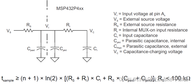
在很难确定外部源的电阻时,一个设置时间转换的实用方法如下:
- 设置你想要的采样频率:Fs
- 设置ADC (Fc)源时钟。使用低频(SAR内的DAC)更佳。
- 计算转换时间:(1/Fc) × 16 = Tc
- 计算Tc与1/ Fs之间的时间差
- 给你尽可能多的时间取样和保存。
6)转换及其模式
单通道单转换
- 外部采样模式:SHI上升边和下降边必须由ADC14ADCSC设置/复位或定时器设置/复位产生,以完成采样并开始转换
- 脉冲采样模式:只需要SHI的上升边缘
- 使用定时器触发转换:ENC位需要在新的转换前触发
- 如果使用软件触发,ENC和ADCSC必须设置在同一条指令中
多通道单转换
- 第一个通道在ADC14CTL1中设置;最后一个要转换的通道在对应的ADC14MCTLx中设置EOS位
- 使用定时器触发转换:ENC位应在开始下一个序列之前被触发
- 要允许转换下一个通道,需要设置位MSC
ADC14CTL0,或触发新的转换(ADCSC或
TimerA / B) - 每次转换写入ADC14MEMx时,都会设置相关标志(只检查最后一次)
单通道多转换
- 在新捕获前从ADCMEMx读取数据。
- 设置MSC,或触发新的转换(ADCSC或
TimerA / B)。
多通道多转换
- 在重新启动之前从内存寄存器读取数据。
- 设置MSC,或触发新的转换(ADCSC或
TimerA / B)
开始转换步骤:
- 设置程序参数,如工作模式、时钟、触发源、MSC位、DC14CTL0和ADC14CTL1等
- 设置
ADCON位以打开转换 - 设置
ENC位以激活转换 - 如果触发源是定时器,转换将在定时器输出边自动开始。
- 如果触发源是软件,设置位
ADCSC。此位将自动清除。注意:ENC和ADC14SC必须用一条指令!如果在扩展采样模式下,在SAMPCON中生成高低边
获取转换的结果:
- 在中断标志寄存器中等待ADC14IFGR0x位。
- 从ADC14MEMx读取数据。
- 读取时ADCI14FGx标志自动清除ADC14MEMx
停止转换:
- 等待忙位重置(在重复和顺序模式中不是强制性的)。
- 复位ENC位。
- 中止:将模式设置为00并重置ENC,数据不可靠。
7)寄存器
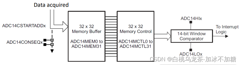
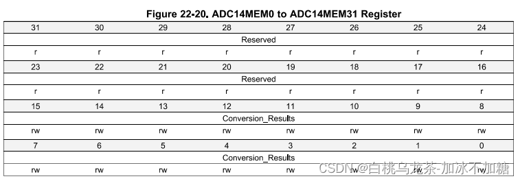
32个32位寄存器ADC14 MEMx用于保存转换结果。任何输入通道都可以存储在任何寄存器中,这简化了不同输入信号的采集。
32个32位寄存器ADC14 MCTLx来控制上述内存寄存器。注意:只在ADC14 ENC=0时可以修改
ADC14 CTL0
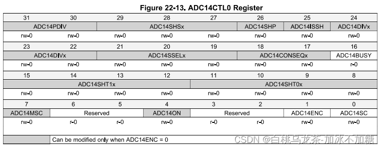
PDIV(31-30):时钟分割器(一级)
DIVx(24-22):时钟分割器(二级)
SSELx(21-19):时钟选择
SHS(29-27):选择采样与保持的数据源
SHP(26):选择采样保持模式,1为脉冲采样模式
SHT1x(用于MEM8~23)和SHT0x(用于其余)(15-8):在SHP=1时选择采样和保持周期。
ON(4):ADC14开关
ENC(1):ADC14使能
SC(0):为1时开始采样-保持-转换
BUSY(16):标志转换正在进行
MSC(7):多次取样或重复
CONSEQx(18-17):选择转换模式(单次、重复、序列)
ADC14 CTL1
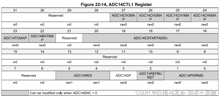
CHxMAP(27-24):控制内部输入通道
TCMAP(23):控制内部温度传感器输入通道
CSTARTADDx(20-16):选择用于转换的第一个内存寄存器
RES(5-4):分辨率(8、10、12、14)
DF(3):数据格式(无符号二进制或2s补码)
REFBURST(2): 参考缓冲区打开/关闭
PWRMD(1-0):正常/低功率
ADC14 MCTLx
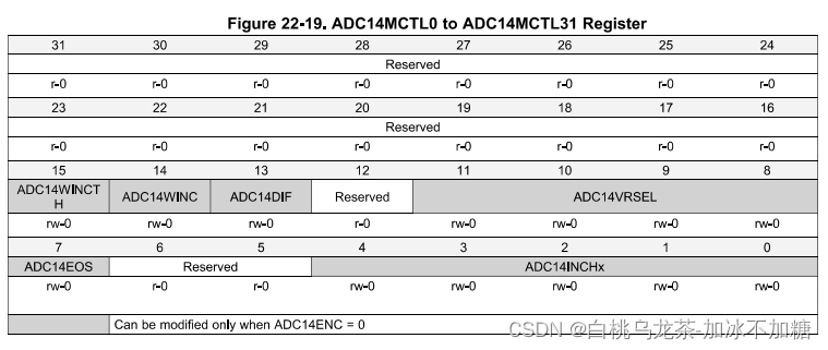
WINCT和WINC(15)(14):控制windows比较器
DIF(13):配置输入为单端或差分
VRSEL(11-8):选择参考电压
EOS(7):表示序列结束
INCHx(4-0):选择物理输入通道
ADC14 MEMx
8)中断
首先需要全局中断和NVIC中断
NVIC_EnableIRQ (ADC14_IRQHandler);
ADC14 IER0
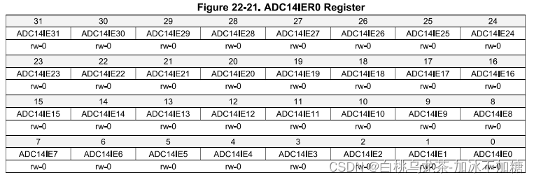
当转换结果存储在寄存器中时,x位对应使能ADC14MEMx的中断
ADC14 IER1
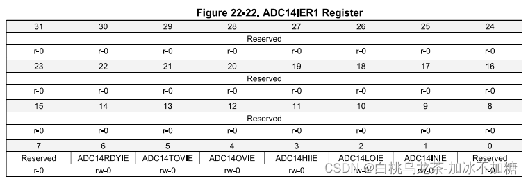
使能特殊事件的中断,如引用准备完成,溢出,窗口比较器限制等。
ADC14 IFGR0
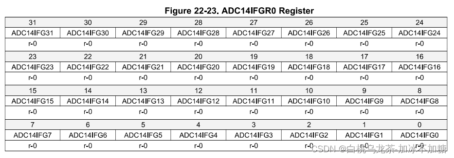
当转换结果存储在ADC14MEMx寄存器中时会设置对应第x位的中断标志;同时,如果ADC14IER0x位被设置,对应中断会被请求。
使用ADC14CLRIFGR0寄存器来清除中断
ADC14 IFGR1
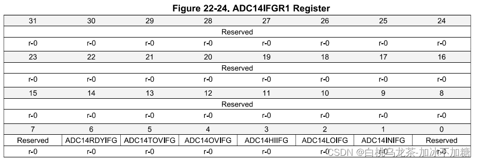
几个特殊事件发生的标志位,如引用准备完成,溢出,窗口比较器限制等。
使用ADC14CLRIFGR1寄存器来清除中断
ADC14 IV
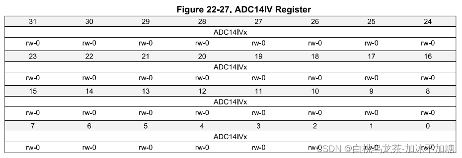
这个寄存器值是ADC14中最高的暂挂中断的编码值
中断处理程序
ADC14_IRQHandler
判断中断来源:
- 读取ADC14IFGR0和ADC14IFGR1
读取完成后清除标志位的方法:- 读ADC14MEMx;
- 或向ADC14CLRIFGR0与ADC14CLRIFGR1中写1
- 读取ADC14IV【更优选择】
查表获得ADC14IV的可能取值,可判断对应中断发生位置
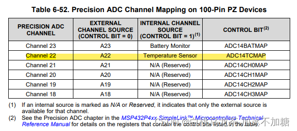
3.7 内部温度传感器
- 连接到通道22并与外部输入多路复用
- 需要打开参考电压来为传感器供电
- 采样和保持必须大于5µS
- 大偏移量(±35ºC)和器件的可变性
3.8 模拟信号与误差
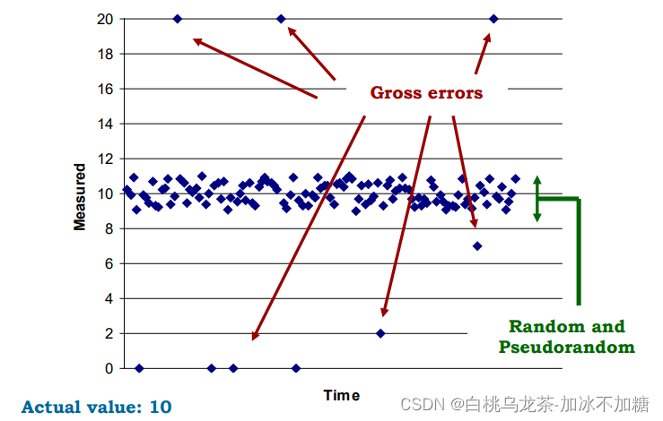
- 测量值永远不等于实际值
绝对误差=|测量值-真实值|
相对误差=|测量值-真实值|/真实值 - 错误种类
- Gross,必须使用统计工具(平均值、中位数、梯度)来丢弃严重误差;
- 随机误差,不可避免;
- 伪随机的、系统的误差,可以过滤或补偿。
- 真实性:大样本集的实际值与平均值之间的距离,通常表示为漂移或偏差
- 精确性:大样本中的可变性,用可重复性和再现性来表示
- 准确率:既真实又精确,通常用跨度或满量程的%表示
- 错误是由于操作员,传感器,信号调理,干扰,温度造成的…
3.9 TimerA与PWM
MSP432P401r有以下定时器:
- Systick
- Watchdog定时器,也可以作为间隔定时器(WDT_A)
- 实时时钟(RTC_C)。
- Timer32。
- Timer_A(最多4个计时器)
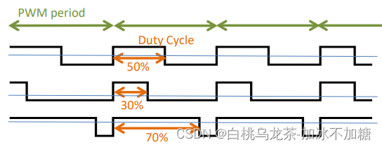
脉宽调制(PWM)
- 通过增加或减少周期信号的高电平周期(调节占空比)来控制输出功率。
- PWM周期取决于被控制的设备
有多达7种捕获/比较块,它们分别是一对寄存器。每个块都关联一个引脚TAx.n。
Up模式下计时器从0计数到TAxCCR0的值,并重复。因此,TAxCCR0的值设置PWM信号的周期。该时间段的具体大小设置则取决于所控制的设备,如Led,直流电机,伺服等,通常是直流供电设备。
当计时器匹配TAxCCRn的值时,输出可能会改变。可以使用几种TAxCCRn同时创造不同的PWM信号和控制不同的器件。

采用TimerA做PWM生成器的方法如下:
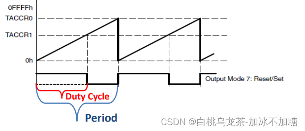
- 选择Up模式
- TAxCCR0保存PWM周期时间
- TAxCCR1保存高电平时间(占空比)
注意:
- 不需要有中断,不需要配置PxSEL0和PxSEL1
- 无法达到0%和100%的占空比
- 定时器可以管理的占空比范围为[5%,95%]
设置极端值的方法:
- 修改输出模式为0
- 手工设置输出值(TAxCCTLn的OUT位)
- 停止计时器,清除TAxR
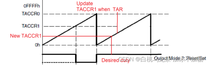
当改变占空比时,如果的新值TAxCCRn低于当前TAR和旧的TAxCCRn,会得到一个全功率的峰值,使用电机、放疗机或其他类型的设备时,这些电源冲程可能会产生故障,损坏设备甚至伤害到人。
解决方案:使用溢出中断以同步方式更新TAxCCRn的值。
每个TA有两个中断向量表
- TAx_0_IRQHandler():用于TAxCCR0的CCIFG,不需要清除flag。
- TAx_N_IRQHandler():用于所有其他中断来源。必须访问TAxIV寄存器,清除相关SFR中的关联标志。如果设置了其他标志中断,则改变TAxIV的值。记住只读取一次TAxIV的值。
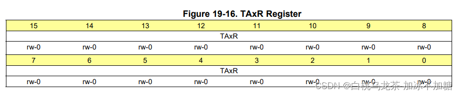
TAxR TimerA的计数器
永远不要访问这个寄存器
TAxCTL TimerA的PWM控制器
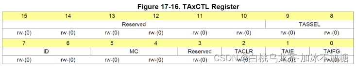
TASSEL(9-8):选择时钟源
ID(7-6):输入时钟分频
MC(5-4):模式选择(Up mode为01)
TACLR(2):清除Timer_A,重置TAR、时钟划分和计数方向。该位一般自动重置因此读数结果常为0。
TAIE(1):Timer_A中断使能
TAIFG(0):Timer_A中断标志
TAxCCRn 存储与计时器的当前计数进行比较的值
在比较输出模式下,当计时器值与TAxCCRx中的值匹配时,数字输出触发。
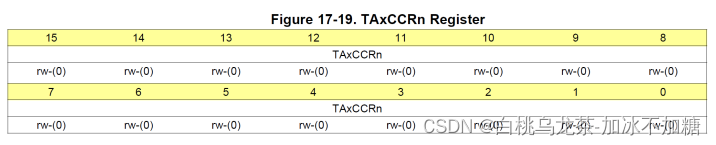
比较模式:TAxCCRn保存与计时器值TAR做比较的数据
捕获模式:在执行捕获时,Timer_A寄存器TAR被复制到TAxCCRn寄存器
TAxCCTLn 配置块n的行为
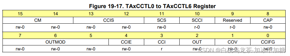
OUTMODx(7-5):输出模式选择(111为Reset/set模式)
OUT(2):在输出模式为000时,1输出high,0输出low
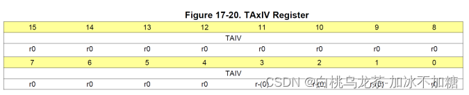
TAxIV
四 文件结构
main.c — 主函数所在文件
startup_msp432p401r_css.c — 中断处理程序的声明
system_msp432p401r.c — 系统初始化,主要是时钟系统
game.h — 游戏库函数
buttons.c — 按钮函数定义
buttons.h — 按钮函数声明
led_control.c — LED函数定义
led_control.h — LED函数声明
analog.c — 模拟输入函数定义
analog.h — 模拟输入函数声明
timer.c — PWM函数定义
timer.h — PWM函数声明
五 代码说明
- DCOCLK设置为24MHz
#define __SYSTEM_CLOCK 24000000 //DCO的频率(Hz),用于MCLK、HSMCLS和SMCLK。 - 菜单中可用选项的数目有3个
#define NUM_OPTIONS 3 - game.h库函数
/* SysTick定时器被配置为每40ms引发一次中断。在游戏循环中调用这个函数允许每40毫秒执行一些任务。* SysTick的ISR将值1设置为一个变量,该变量是库的私有变量,称为SysTick_flag。* 这个函数返回值Systick_flag,随后将其清除为0。*/ uint8_t check_SysTick_flag(void); /* 初始化TFT屏幕和软件结构来创建游戏。* 此函数启用了全局中断。*/ void Init_Game(void); /* 在屏幕上绘制游戏菜单。* 在进入菜单管理循环之前只调用一次。*/ void Create_Menu(void); /* 高亮显示由参数选项指示的所选颜色。* 如果选项不在 [0, NUM_OPTIONS -1] 的范围内,则不执行任何操作。*/ uint8_t Show_Menu(uint8_t option); /* 存储用户选择的汽车颜色,以便在游戏开始时使用。* 它是一个与菜单中选项的数字相对应的数字,如果参数不在 [0, NUM_OPTIONS -1] 的范围内,则行为是未定义的*/ void Set_Car_Color (uint8_t color); /* 在屏幕上绘制汽车。它必须每40毫秒调用一次 */ void Draw_Car(void); /* 在屏幕上绘制道路。它必须每40毫秒调用一次 */ void Draw_Road(void); /* 在参数偏移量中指定的单位中更改汽车的存储位置。* 如果offset值为负,则位置向左移动。如果offset值为正,则位置向右移动。* 这个函数不会更新汽车在屏幕上的位置。*/ void Steering_Wheel (int8_t offset); /* 在参数单位中指定的单位中更改汽车的存储速度。* 如果单位值为负,则速度降低。单位值为正,速度提高。* 该函数注意保持速度在允许的最小和最大速度范围内。这个函数不更新屏幕。*/ uint8_t change_speed(uint8_t units); /* 在屏幕上显示字符串l1和l2,用于显示报错信息。 */ void show_error(int8_t *l1, int8_t *l2); - 游戏结构分为两个循环:
- 菜单循环:允许用户选择汽车的颜色并开始游戏。
- 游戏循环:运行游戏(绘制道路并向前移动汽车)。它是一个时间触发的结构。
void main(void){uint8_t menu, menu_option, game, error;WDT_A->CTL = WDT_A_CTL_PW | WDT_A_CTL_HOLD; // Stop WDT// Enable global interrupt and initialize_enable_interrupts(); Init_Game();while (1){Create_Menu();menu = 1; //The menu is runningwhile (menu){error = Show_Menu(menu_option);if (error){show_error("PARAM", "ERROR");}// Go down the menu if bottom button is pressed// Choose the color if the upper buttons is pressed// If joystick button end menu loop and go to next loop}}Init_Game ();game = 1;while (game){if (check_SysTick_flag()){ // SysTick event every 40msDraw_Road();Draw_Car();// If upper button is pressed, update speed// If joystick button is pressed, end game loop// Using the analog joystick, move car left and right}
}
六 任务与实现
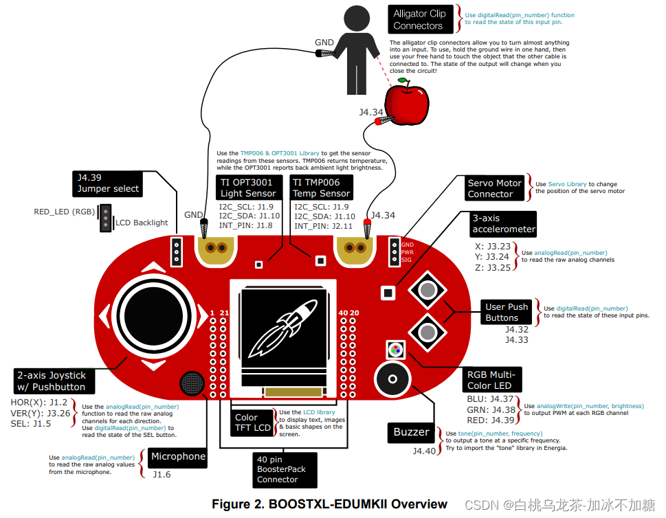
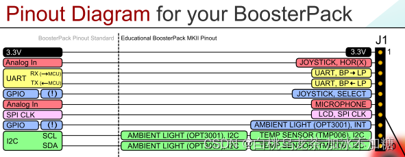
6.1 硬件说明
| 部件 | MKII booster pack引脚与端口 | MSP432P401R引脚与端口 | 模拟通道 | 定时器输出 |
|---|---|---|---|---|
| Bottom按键 | J4.32 | P3.5 | ||
| Upper按键 | J4.33 | P5.1 | ||
| Joystick按键 | J1.5 | P4.1 | ||
| Joystick-X | J1.2 | P6.0 | A15 | |
| Joystick-Y | J3.26 | P4.4 | A9 | |
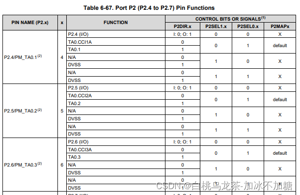
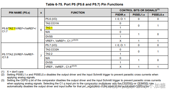
| RGB-BLU | J4.37 | P5.6 | TA2.1 | |
| RGB-GRN | J4.38 | P2.4 | TA0.1 | |
| RGB-RED | J4.39 | P2.6 | TA0.3 | |
| accelerometer-X | J3.23 | P6.1 | A14 | |
| accelerometer-Y | J3.24 | P4.0 | A13 | |
| accelerometer-Z | J3.25 | P4.2 | A11 | |
| Ti TMP006 温度传感器-时钟 | J1.9 | P6.5 | ||
| Ti TMP006 温度传感器-数据 | J1.10 | P6.4 | A22 |
* From MKII_start_guide.pdf, MSP‑EXP432P401R_guide.pdf and MKII_users_guide.pdf

6.2 按键
按键初始化
/*** configure the bottom button* Parameters: none.* Return value: none.* Note: have real pull-up resistors on the board so don't need these:* 		Px->REN |= BITx; // register enablePx->OUT |= BITx; // set as pull-up register*/
void init_buttons (void){// bottom buttonP3->SEL0 &= ~BIT5;P3->SEL1 &= ~BIT5;  // set I/O function to GPIOP3->DIR &= ~BIT5;   // set pin as input// upper buttonP5->SEL0 &= ~BIT1;P5->SEL1 &= ~BIT1;  // set I/O function to GPIOP5->DIR &= ~BIT1;   // set pin as input// joystick buttonP4->SEL0 &= ~BIT1;P4->SEL1 &= ~BIT1;  // set I/O function to GPIOP4->DIR &= ~BIT1;   // set pin as input
}
按键中断初始化
- PxIES设置中断边缘
- PxIFG清除中断标志(必须在中断开启之前)
- 依次打开三级中断
__set_PRIMASK(0); 				//enable global interrupts
NVIC_EnableIRQ (PORTx_IRQn);    //enable Port x interrupts
Px->IE |= BITk;                 //enable Pin k of Port x interrupts
/*** configure the buttons and enable their interrupt* Parameters: none.* Return value: none.* Note: function _enable_interrupts() in main.c do the same as this:*      __set_PRIMASK(0); // enable global interrupts*/
void init_buttons_int (void){init_buttons();// bottom buttonP3->IES |= BIT5;                // set a interrupt edge select of high-to-low, should be the first thing before others.P3->IFG &= ~BIT5;               // clear the interrupts flag of Port 3NVIC_EnableIRQ (PORT3_IRQn);    // enable Port 3 interruptsP3->IE |= BIT5;                 // enable Pin 5 of Port 3 interrupts// upper buttonP5->IES |= BIT1;                // set a interrupt edge select of high-to-low, should be the first thing before others.P5->IFG &= ~BIT1;               // clear the interrupts flag of Port 5NVIC_EnableIRQ (PORT5_IRQn);    // enable Port 5 interruptsP5->IE |= BIT1;                 // enable Pin 1 of Port 5 interrupts// joystick buttonP4->IES |= BIT1;                // set a interrupt edge select of high-to-low, should be the first thing before others.P4->IFG &= ~BIT1;               // clear the interrupts flag of Port 4NVIC_EnableIRQ (PORT4_IRQn);    // enable Port 4 interruptsP4->IE |= BIT1;                 // enable Pin 1 of Port 4 interrupts
}
读按键值
由于文档中指出该按键硬件层面上存在上拉电阻,由此没有被按下时保持高电平。
检查PxIN寄存器的对应位,为0时代表按下,函数返回1。
/*** read the state of the bottom button* Parameters: none.* Return value: 0 if button_bottom is not pressed, otherwise it returns 1*/
uint8_t read_button_bottom (void){if((P3->IN & BIT5) == 0){ return 1; } //button is pressedelse { return 0; } // button is not pressed
}
/*** read the state of the upper button* Parameters: none.* Return value: 0 if button_upper is not pressed, otherwise it returns 1*/
uint8_t read_button_upper (void){if((P5->IN & BIT1) == 0){ return 1; } // button is pressedelse { return 0; } // button is not pressed
}
重复检测与除颤
- 状态机
这种做法显然会造成颜色选择困难,因为我们检查按钮状态的速度比用户按下和释放按钮的速度要快得多。这样一个按钮的激活数就被计算为多个。事实上,我们不想知道输入的电平(高或低),我们想检测的是转换,也就是输入上的边。软件解决方案是使用有限状态机(FSM),也被称为状态机或有限自动机。//main.c if ( read_button_bottom() == 1 ){ // Go down the menu if bottom button is pressedmenu_option = (menu_option + 1) % 3; // Add 1 to menu_option taking care that there are 3 options }
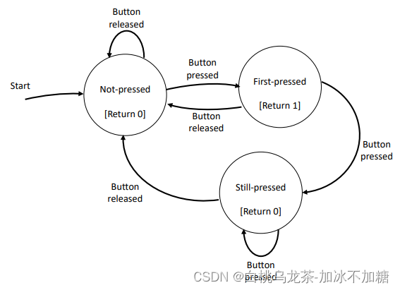
//main.c
if (button_bottom_fsm() == 1){ // Go down the menu if bottom button is pressedmenu_option = (menu_option + 1) % 3; // Add 1 to menu_option taking care that there are 3 options
}
注意:一个激活仍然可以被检测到两次或三次。这是由于硬件反弹。硬件反弹可以通过软件最小化,并使用低通RC滤波器消除。/*** detect the bottom button by a finite-state-machine* Parameters: none.* Return value: 1 if button_bottom is first-pressed, otherwise it returns 0*/ uint8_t button_bottom_fsm (void){static uint8_t pressed_state = 0; // 注意pressed_state只能被初始化一次且在调用函数之间需要保持值不变,由此声明为static变量uint8_t tag = 0; // 用于标记按钮是否首次按下。1为是第一次按下,0为不是。switch(pressed_state){case 0:if (read_button_bottom() == 1){ pressed_state = 1; }break;case 1:if (read_button_bottom() == 1){ pressed_state = 2; }else { pressed_state = 0; }tag = 1;break;case 2:if (read_button_bottom() == 0){ pressed_state = 0; }break;default: {}break;}return tag; // tag即返回值 } - 中断
中断可以自动检测输入信号的边缘。- 方法一:读取PxIFG,检查哪个引脚引发了中断,然后清除相应的位。
- 方法二:读取PxIV,会自动清除IFG标志位。注意每次读取寄存器都会更新,也就是说只能读取一次寄存器。
/** ISR to handle the interrupt when the bottom button is pressed.(use PxIFG)* Parameters: none.* Return value: none.*/
void PORT3_IRQHandler (void){if((P3->IFG & BIT5) != 0){    // if the bottom button is pressedP3->IFG &= ~BIT5;         // clear the corresponding flagbutton_bottom_flag = 1;   // set the global variable}
}
/** ISR to handle the interrupt when the upper button is pressed.(use PxIV)* Parameters: none.* Return value: none.*/
void PORT5_IRQHandler (void){switch (P5->IV){case DIO_PORT_IV__IFG1:button_upper_flag = 1;    // set the global variablebreak;default:break;}
}
/** ISR to handle the interrupt when the joystick button is pressed.(use PxIV)* Parameters: none.* Return value: none.*/
void PORT4_IRQHandler (void){switch (P4->IV){case DIO_PORT_IV__IFG1:button_joystick_flag = 1;  // set the global variablebreak;default:break;}
}
PS.多文件全局变量声明
// buttons.h
extern uint8_t button_bottom_flag; /* 声明 */
// buttons.c
uint8_t button_bottom_flag = 0; /* 初始化 */
// main.c
/*直接使用*/
原子操作消除冲突
检查作标志的变量button_bottom_flag,拷贝它的值,随后清除变量。
上述操作必须在禁用中断的时候完成。禁用和恢复全局中断涉及以下两个函数。
uint32_t _disable_interrupts(); // Returns previous value of PRIMASK and set it to 1
void _restore_interrupts (uint32_t priMask) // Set PRIMASK to value priMask
注意:操作结束后必须恢复而不是简单地启用中断。另外,可以选择禁用所有的中断,或者只是禁用相关的中断(如端口x的PIN k),但在本例中必须全部禁用以保证操作的原子性。
/** get the value of button_bottom_flag, an atomic section of code.* Parameters: none.* Return value: the copy of button_bottom_flag*/
uint8_t check_and_clear_bb_flag (void){uint32_t int_state = _disable_interrupts(); // disable global interrupts and save the STAT of PRIMASKuint8_t flag = button_bottom_flag;          // copy button_bottom_flagbutton_bottom_flag = 0;                     // clear button_bottom_flag_restore_interrupts (int_state);            // Set PRIMASK to value priMask:int_statereturn flag;
}
全局变量button_xx_flag需要从全局变量修改为静态变量,只有通过对应的操作函数才能读取。
#define BUTTON_BOTTOM 0
#define BUTTON_UPPER 1
#define BUTTON_JOYSTICK 2static uint8_t button_bottom_flag = 0;
static uint8_t button_upper_flag = 0;
static uint8_t button_joystick_flag = 0;/** get the value of button flag, an atomic section of code.* Parameters: button_code which 0 is bottom button, 1 is upper button and 2 is joystick button.* Return value: the copy of button flag*/
uint8_t check_and_clear_button_flag (uint8_t button_code){uint32_t int_state = _disable_interrupts(); // disable global interrupts and save the STAT of PRIMASKuint8_t flag;switch(button_code){case BUTTON_BOTTOM:flag = button_bottom_flag;button_bottom_flag = 0;break;case BUTTON_UPPER:flag = button_upper_flag;button_upper_flag = 0;break;case BUTTON_JOYSTICK:flag = button_joystick_flag;button_joystick_flag = 0;break;default:break;}_restore_interrupts (int_state);            // Set PRIMASK to value priMask:int_statereturn flag;
}
主函数
void main(void)
{uint8_t menu, menu_option, game, error;WDT_A->CTL = WDT_A_CTL_PW | WDT_A_CTL_HOLD;   // Stop WDT// Enable global interrupt and initialize_enable_interrupts();Init_Game(); init_buttons_int();while (1){  //Super LoopCreate_Menu();menu = 1;  // The menu is runningwhile (menu){error = Show_Menu(menu_option);if (error){show_error("PARAM", "ERROR");}if (check_and_clear_button_flag(BUTTON_BOTTOM) == 1){ // Go down the menu if bottom button is pressedmenu_option = (menu_option + 1) % 3; // Add 1 to menu_option taking care that there are 3 options}if (check_and_clear_button_flag(BUTTON_UPPER) == 1){ // Choose the color if the upper button is pressedif((menu_option < 0) || (menu_option > 2)) { show_error("COLOR", "ERROR"); } // Check the correctness of the parameter.Set_Car_Color(menu_option); // Call library function Set_Car_Color.}if (check_and_clear_button_flag(BUTTON_JOYSTICK) == 1){ // End menu loop and go to next loop if joystick button is pressedif((menu_option < 0) || (menu_option > 2)) { show_error("COLOR", "ERROR"); } // Check the correctness of the menu_option.menu = 0; // End the menu loop}}Init_Game ();game = 1; while (game){if (check_SysTick_flag()){ // SysTick event every 40msDraw_Road();Draw_Car();if (read_button_bottom() == 1){ // Update speed if bottom button is pressedchange_speed(-1); // Call library function to decrease speed one unit}if (read_button_upper() == 1){ // Update speed if upper button is pressedchange_speed(1); // Call library function to increase speed one unit}if(check_and_clear_button_flag(BUTTON_JOYSTICK) == 1){ // End game loop if joystick button is pressedgame = 0; // End the game loop}}}}
}
6.3 LED
LED初始化
/*** configure the leds* Parameters: none.* Return value: none.*/
void init_rgb(void){// redP2->SEL0 &= ~BIT6;P2->SEL1 &= ~BIT6;  // set I/O function to GPIOP2->DIR |= BIT6;    // set pin as output// greenP2->SEL0 &= ~BIT4;P2->SEL1 &= ~BIT4;  // set I/O function to GPIOP2->DIR |= BIT4;    // set pin as output// blueP5->SEL0 &= ~BIT6;P5->SEL1 &= ~BIT6;  // set I/O function to GPIOP5->DIR |= BIT6;    // set pin as output
}
开灯
/*** set the led on related to the menu option choose by the user* Parameters: color.* Return value: none.*/
void led_on(uint8_t color){switch(color){case 0:P2->OUT |= BIT6;    	// redP2->OUT &= ~BIT4;     	// greenP5->OUT &= ~BIT6;     	// bluebreak;case 1:P2->OUT &= ~BIT6; 		// redP2->OUT |= BIT4; 		// greenP5->OUT &= ~BIT6; 		// bluebreak;case 2:P2->OUT &= ~BIT6; 		// redP2->OUT &= ~BIT4; 		// greenP5->OUT |= BIT6; 		// bluebreak;default: {}break;}
}
关灯
/*** switch off the three leds.* Parameters: none.* Return value: none.*/
void led_off(void){P2->OUT &= ~BIT6; // redP2->OUT &= ~BIT4; // greenP5->OUT &= ~BIT6; // blue
}
6.4 ADC14 - 内部温度传感器
采样保持的模式:脉冲采样模式,ADC14SHP=1
ADC14CLK频率 = 1 /(采样周期/采样周期数)。其中采样周期必须大于5微秒,采样周期数可从4至192个周期。
本项目中系统时钟位24MHz,设置ADC14CLK频率 = HSMCLK / 2 = 12MHz,可选择64个采样周期数(5.3微秒的采样周期)或96个采样周期数(8微秒的采样周期)。
ADC14初始化(single-channel single-conversion operation mode)
- 清除CTL0和CTL1,确保无关位为0;
- 配置时钟(SSEL:clock source,PDIV:pre-dividing,DIV:dividing)
- 选择采样模式:脉冲采样模式(SHP=1),选择操作模式:单通道单转换(CONSEQ=00)
- 采样周期数(SHT0)
- 打开开关(ON)
- 设置目标寄存器存放结果(CSTARTADD)
- 设置分辨率(RES)
/*** configure the ADC* Parameters: none.* Return value: none.*/
void init_adc14(void) {/* Clear all */ADC14->CTL0 = 0;ADC14->CTL1 = 0;/* Select HSMCLK as clock source for ADC14CLK, pre-dividing by 1 and dividing by 2 */ADC14->CTL0 |= ADC14_CTL0_SSEL__HSMCLK | ADC14_CTL0_PDIV__1 | ADC14_CTL0_DIV__2;/* Select ADC14SC bit to start a conversion, select Pulse Sample Mode, and single-channel single-conversion operation mode */ADC14->CTL0 |= ADC14_CTL0_SHP | ADC14_CTL0_CONSEQ_0;/* Select 96 sampling periods for ADC14MEM0 */ADC14->CTL0 |= ADC14_CTL0_SHT0__96;/* Switch on the ADC, leave ENC and other bits of ADC14CTLO to 0. */ADC14->CTL0 |= ADC14_CTL0_ON;/* Set the conversion address start to ADC14MEM0. */ADC14->CTL1 |= (0 << ADC14_CTL1_CSTARTADD_OFS);/* Set the ADC14 resolution to 14 bits. */ADC14->CTL1 |= ADC14_CTL1_RES0 | ADC14_CTL1_RES1;
}
温度传感器初始化
- 选择内部温度传感器输入(TCMAP)
- 打开温度传感器选择电压参考
- 选择参考电压模式(VRSEL=00:Vref+ = Vcc and Vref- = Vss)设置通道(INCH)
- 通过读寄存器确保中断标志位清除
/*** configure the temperature sensor* Parameters: none.* Return value: none.*/
void config_temp(void){/* Select in ADC14CTL1 the temperature sensor, setting the bit ADC14TCMAP. */ADC14->CTL1 |= ADC14_CTL1_TCMAP;/* Switch on the voltage reference and enable powering the temperature sensor */REF_A->CTL0 |= REF_A_CTL0_ON;REF_A->CTL0 &= ~REF_A_CTL0_TCOFF;/* Configure register ADC14MCTL0 (0 because we choose it) selecting the voltage reference Vref+ = Vcc and Vref- = Vss) and set the input channel. */ADC14->MCTL[0] |= ADC14_MCTLN_VRSEL_0 | ADC14_MCTLN_INCH_22;/* Read the register ADC14MEM0 and discard the reading, this way you are sure the corresponding IFG bit is cleared. */ADC14->MEM[0];
}
温度传感器读数
脉冲采样模式:需要SHI的上升边缘(将ENC清零产生)
使用软件触发:ENC和ADCSC必须设置在同一条指令中(开始进行采样-保持-转换)
/*** clear the ENC bit (to create a low to high transition) and start the conversion (setting ENC and SC bits). Then, wait in a loop until the bit 0 in IFG is set.* Parameters: none.* Return value: the value of ADC14MEM0*/
uint16_t read_temp(void){ADC14->CTL0 &= ~ADC14_CTL0_ENC;ADC14->CTL0 |= ADC14_CTL0_ENC | ADC14_CTL0_SC;while((ADC14->IFGR0 & ADC14_IFGR0_IFG0) == 0){};return ADC14->MEM[0];
}
结果转换
参考电压为0~3.3V,数字输出转化为电压输出的计算公式为:(结果/16384)*3.3。
注意:这里要首先对结果进行类型转换(uint16_t 到float),否组/16384的计算结果会因C语言的数据类型语法产生错误。
/*** receives the value read by the ADC and convert it to volts* Parameters: the value read by the ADC* Return value: the volts conversion result*/
float convert_to_volts (uint16_t reading){return ((float)reading / 16384) * 3.3;
}
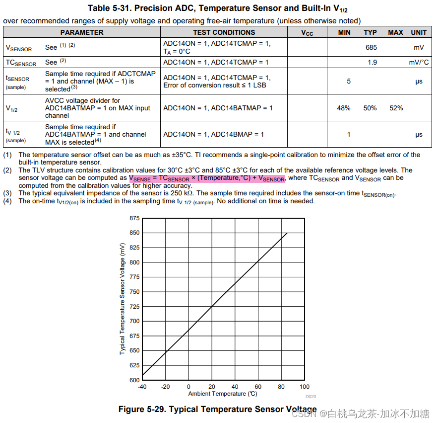
温度传感器电压的特征方程(毫伏)为:
V_sense = TC_sensor × Temp + V_sensor
则温度(摄氏度)为:
Temp = (V_sense - V_sensor) / TC_sensor = (V_sense - 685(mV)) / 1.9(mV/℃)
/*** receives the value read by the ADC converted to volts and convert it to grades Celsius* Parameters: the value read by the ADC* Return value: the volts conversion result*/
float convert_to_Celsius (float volts){return (volts * 1000 - 685) / 1.9;
}
指针(引用)传参
/*** receives the value read by the ADC converted to volts and convert it to grades Celsius with passing parameters by reference* Parameters: the address of the values* Return value:  the reading from the ADC, its conversion to volts and its conversion to Celsius*/
void all_values_temp(uint16_t * temp, float * temp_volts, float * temp_celsius){ // *表指针(*temp) = read_temp();(*temp_volts) = convert_to_volts(*temp);(*temp_celsius) = convert_to_Celsius(*temp_volts); // *表指针所指的内存单元
}
主函数
#include <stdio.h>
#include "msp.h"
#include "analog.h"/*** main.c*/
void main(void)
{uint16_t ans = 0;float ans2 = 0, ans3 = 0;WDT_A->CTL = WDT_A_CTL_PW | WDT_A_CTL_HOLD;		// stop watchdog timerinit_adc14();config_temp();while(1){all_values_temp(&temp, &temp_volts, &temp_celsius); // &表变量的地址,用作指针printf("ADC: %d\n", temp);printf("ADC (volts): %f\n", temp_volts);printf("ADC (celsius): %f\n", temp_celsius);}
}
6.5 ADC14 - 加速度模块
ADC14初始化(sequence-of-channels mode)
见6.6
加速度模块初始化
- ENC清零,是保证修改部分控制位的前提条件
- 配置加速度模块的XYZ三个端口为第三种功能模式,且作输入引脚
- 选择参考电压模式(VRSEL=00:Vref+ = Vcc and Vref- = Vss)设置通道(INCH)
- 通过读寄存器确保中断标志位清除
void config_accel(void){ADC14->CTL0 &= ~ADC14_CTL0_ENC;/* Configure registers ADC14MCTL3 and ADC14MCTL4 selecting the voltage reference Vref+ = Vcc and Vref- = Vss) and set the input channel. */ADC14->MCTL[3] |= ADC14_MCTLN_VRSEL_0 | ADC14_MCTLN_INCH_14;ADC14->MCTL[4] |= ADC14_MCTLN_VRSEL_0 | ADC14_MCTLN_INCH_13;ADC14->MCTL[5] |= ADC14_MCTLN_VRSEL_0 | ADC14_MCTLN_INCH_11;/* Read the register ADC14MEM and discard the reading, this way you are sure the corresponding IFG bit is cleared. */ADC14->MEM[3];ADC14->MEM[4];ADC14->MEM[5];// axis xP6->SEL0 |= BIT1;P6->SEL1 |= BIT1;       // set I/O function to tertiary functionP6->DIR &= ~BIT1;       // set pin as input// axis yP4->SEL0 |= BIT0;P4->SEL1 |= BIT0;       // set I/O function to tertiary functionP4->DIR &= ~BIT0;       // set pin as input// axis zP4->SEL0 |= BIT2;P4->SEL1 |= BIT2;       // set I/O function to tertiary functionP4->DIR &= ~BIT2;       // set pin as input
}
加速度模块读数
脉冲采样模式:需要SHI的上升边缘(将ENC清零产生)
使用软件触发:ENC和ADCSC必须设置在同一条指令中(开始进行采样-保持-转换)
注意:采用多通道单采样时,只需要检测最后一个完成的通道标志位
void read_accel(uint16_t * xx, uint16_t * yy, uint16_t * zz){/* clear the ENC bit (to create a low to high transition) and start the conversion (setting ENC and SC bits). */ADC14->CTL0 &= ~ADC14_CTL0_ENC;ADC14->CTL0 |= ADC14_CTL0_ENC | ADC14_CTL0_SC;/* wait in a loop until the bit 0 in IFG is set. */while((ADC14->IFGR0 & ADC14_IFGR0_IFG5) == 0){};(*xx) = ADC14->MEM[3];(*yy) = ADC14->MEM[4];(*zz) = ADC14->MEM[5];
}
主函数
/*** main.c*/
void main(void)
{uint16_t xx = 0, yy = 0, zz = 0;WDT_A->CTL = WDT_A_CTL_PW | WDT_A_CTL_HOLD;		// stop watchdog timerinit_adc14();config_accel();while(1){read_accel(&xx, &yy, &zz);printf("xx: %d; yy: %d; zz: %d\n", xx, yy, zz);}
}
6.6 ADC14 - Joystick操作杆
ADC14初始化(sequence-of-channels mode)
- 清除CTL0和CTL1,确保无关位为0;
- 配置时钟(SSEL:clock source,PDIV:pre-dividing,DIV:dividing)
- 选择采样模式:脉冲采样模式(SHP=1),选择操作模式:单通道单转换(CONSEQ=01、MSC)
- 采样周期数(SHT0)
- 打开开关(ON)
- 设置目标寄存器存放结果(CSTARTADD)
- 设置分辨率(RES)
/*** configure the ADC* Parameters: none.* Return value: none.*/
void init_adc14(void) {/* Clear all */ADC14->CTL0 = 0;ADC14->CTL1 = 0;/* Select HSMCLK as clock source for ADC14CLK, pre-dividing by 1 and dividing by 2 */ADC14->CTL0 |= ADC14_CTL0_SSEL__HSMCLK | ADC14_CTL0_PDIV__1 | ADC14_CTL0_DIV__2;/* Select ADC14SC bit to start a conversion, select Pulse Sample Mode, and sequence-of-channels mode */// ADC14->CTL0 |= ADC14_CTL0_SHP | ADC14_CTL0_CONSEQ_0; // single-channel single-conversion operation modeADC14->CTL0 |= ADC14_CTL0_SHP | ADC14_CTL0_CONSEQ_1;ADC14->CTL0 |= ADC14_CTL0_MSC;/* Select 96 sampling periods for ADC14MEM0 */ADC14->CTL0 |= ADC14_CTL0_SHT0__96;/* Switch on the ADC, leave ENC and other bits of ADC14CTLO to 0. */ADC14->CTL0 |= ADC14_CTL0_ON;/* Set the conversion address start to ADC14MEM3. */// ADC14->CTL1 |= (0 << ADC14_CTL1_CSTARTADD_OFS); // ADC14MEM0ADC14->CTL1 |= (1 << ADC14_CTL1_CSTARTADD_OFS) | (1 << (ADC14_CTL1_CSTARTADD_OFS + 1)); // ADC14->CTL1 |= (3 << ADC14_CTL1_CSTARTADD_OFS);/* stop the sequence of conversion */ADC14->MCTL[4] |= ADC14_MCTLN_EOS;/* Set the ADC14 resolution to 14 bits. */ADC14->CTL1 |= ADC14_CTL1_RES__14BIT; // ADC14_CTL1_RES0 | ADC14_CTL1_RES1;
}
Joystick操作杆初始化
- ENC清零,是保证修改部分控制位的前提条件
- 配置Joystick的XY两个端口为第三种功能模式,且作输入引脚
- 选择参考电压模式(VRSEL=00:Vref+ = Vcc and Vref- = Vss)设置通道(INCH)
- 通过读寄存器确保中断标志位清除
/*** configure all the registers related to the Joystick* Parameters: none* Return value:  none*/
void config_joystic (void){ADC14->CTL0 &= ~ADC14_CTL0_ENC; // 确保可以修改SFR/* Configure registers ADC14MCTL3 and ADC14MCTL4 selecting the voltage reference Vref+ = Vcc and Vref- = Vss) and set the input channel. */ADC14->MCTL[3] |= ADC14_MCTLN_VRSEL_0 | ADC14_MCTLN_INCH_15;ADC14->MCTL[4] |= ADC14_MCTLN_VRSEL_0 | ADC14_MCTLN_INCH_9;/* Read the register ADC14MEM and discard the reading, this way you are sure the corresponding IFG bit is cleared. */ADC14->MEM[3];ADC14->MEM[4];// axis xP6->SEL0 |= BIT0;P6->SEL1 |= BIT0;       // set I/O function to tertiary functionP6->DIR &= ~BIT0;       // set pin as input// axis yP4->SEL0 |= BIT4;P4->SEL1 |= BIT4;       // set I/O function to tertiary functionP4->DIR &= ~BIT4;       // set pin as input
}
Joystick操作杆读数
脉冲采样模式:需要SHI的上升边缘(将ENC清零产生)
使用软件触发:ENC和ADCSC必须设置在同一条指令中(开始进行采样-保持-转换)
注意:采用多通道单采样时,只需要检测最后一个完成的通道标志位
/*** read the value of axis x and y of the joystick* Parameters: the address of the return values* Return value:  returns in parameters the reading of axis x and y of the joystick*/
void read_joystick(uint16_t * xx, uint16_t * yy){/* clear the ENC bit (to create a low to high transition) and start the conversion (setting ENC and SC bits). */ADC14->CTL0 &= ~ADC14_CTL0_ENC;ADC14->CTL0 |= ADC14_CTL0_ENC | ADC14_CTL0_SC;/* wait in a loop until the bit 0 in IFG is set. */while((ADC14->IFGR0 & ADC14_IFGR0_IFG4) == 0){};(*xx) = ADC14->MEM[3];(*yy) = ADC14->MEM[4];
}
主函数
#include <stdint.h>
#include <stdio.h>
#include "msp.h"
#include "game.h"
#include "buttons.h"
#include "led_control.h"
#include "analog.h"/*** main.c*/
void main(void)
{// Declaration of variablesuint8_t menu, menu_option, game, error;uint16_t xx = 0, yy = 0;WDT_A->CTL = WDT_A_CTL_PW | WDT_A_CTL_HOLD;   // Stop WDT// Enable global interrupt and initialize_enable_interrupts();Init_Game(); //Requires interruptsinit_buttons_int();init_rgb();init_adc14();config_joystic();while (1){  //Super LoopCreate_Menu();menu = 1;  // The menu is runningwhile (menu) {error = Show_Menu(menu_option);if (error){show_error("PARAM", "ERROR");}if (check_and_clear_button_flag(BUTTON_BOTTOM) == 1){ // Go down the menu if bottom button is pressedmenu_option = (menu_option + 1) % 3; // Add 1 to menu_option taking care that there are 3 options}if (check_and_clear_button_flag(BUTTON_UPPER) == 1){ // Choose the color if the upper button is pressedif((menu_option < 0) || (menu_option > 2)) { show_error("COLOR", "ERROR"); } // Check the correctness of the parameter.Set_Car_Color(menu_option); // Call library function Set_Car_Color.led_on(menu_option);}if (check_and_clear_button_flag(BUTTON_JOYSTICK) == 1){ // End menu loop and go to next loop if joystick button is pressedif((menu_option < 0) || (menu_option > 2)) { show_error("COLOR", "ERROR"); } // Check the correctness of the menu_option.menu = 0; // End the menu loop}}led_off();Init_Game ();game = 1; // Let's play!!!while (game){if (check_SysTick_flag()){ // SysTick event every 40msDraw_Road();Draw_Car();if (read_button_bottom() == 1){ // Update speed if bottom button is pressedchange_speed(-1); // Call library function to decrease speed one unit}if (read_button_upper() == 1){ // Update speed if upper button is pressedchange_speed(1); // Call library function to increase speed one unit}if (check_and_clear_button_flag(BUTTON_JOYSTICK) == 1){ // End game loop if joystick button is pressedgame = 0; // End the game loop}read_joystick(&xx, &yy);//printf("xx: %d; yy: %d\n", xx, yy);if(yy > 14000){ change_speed(1); }else if(yy < 2000){ change_speed(-1); }if(xx > 14000){ Steering_Wheel(1); }else if(xx < 3000){ Steering_Wheel(-1); }}}}
}
加速比例映射
x的范围约为470-16384;y的范围约为0-16384。实现根据操纵杆的位置对方向盘和速度进行比例控制。
read_joystick(&xx, &yy);
v_speed = yy / 3277 - 2; // divide the speed into five levels: [-2, 2]
if((v_speed < -2) || (v_speed > 2)) { show_error("JOYSICK", "ERROR"); } // Check the correctness of v_speed
change_speed(v_speed*3); // change the speed according to the level. (-6 -3 0 +3 +6)v_wheel = (xx - 470) / 3183 - 2; // divide the wheel into five levels: [-2, 2]
if((v_wheel < -2) || (v_wheel > 2)) { show_error("JOYSICK", "ERROR"); } // Check the correctness of v_wheel
Steering_Wheel(v_wheel); // change the wheel according to the level. (-2 -1 0 +1 +2)printf("xx: %d, yy: %d, v_speed: %d, v_wheel: %d\n", xx, yy, v_speed*3, v_wheel);
6.7 TimerA - PWM LED
PWM初始化
- 选择LED的功能模块为SEL0=1,SEL1=0;端口为输出端口DIR=1
- 时钟设置(CTL里SSEL、ID)
- 选择Up模式(CTL里MC位)
- 设置PWM周期(CCR0)与占空比(CCRx)
- 设置输出模式为Reset/set模式(CCTLx里OUTMOD)
/*** configure the digital pin and the timer (blue)* Parameters: none.* Return value: none.*/
void config_blue_pwm(void){// set I/O function to TA2.1P5->SEL0 |= BIT6;P5->SEL1 &= ~BIT6;P5->DIR |= BIT6;// Use SMCLK (24MHz) divided by 4 as clock source for the timerTIMER_A2->CTL |= TIMER_A_CTL_SSEL__SMCLK | TIMER_A_CTL_ID__4;// Select Up modeTIMER_A2->CTL |= TIMER_A_CTL_MC__UP;// Set TAxCCR0 the value for PWM periodTIMER_A2->CCR[0] = 7500;// Set TAxCCR1 the value for active timeTIMER_A2->CCR[1] |= TIMER_A2->CCR[0] >> 2; //除以4,默认占空比为25%// Set output mode in 7TIMER_A2->CCTL[1] |= TIMER_A_CCTLN_OUTMOD_7;
}/*** configure the digital pin and the timer (red and green)* Parameters: none.* Return value: none.*/
void config_red_green_pwm(void){// set I/O function to TA0.1P2->SEL0 |= BIT4;P2->SEL1 &= ~BIT4;P2->DIR |= BIT4;// set I/O function to TA0.3P2->SEL0 |= BIT6;P2->SEL1 &= ~BIT6;P2->DIR |= BIT6;// Use SMCLK (24MHz) divided by 4 as clock source for the timerTIMER_A0->CTL |= TIMER_A_CTL_SSEL__SMCLK | TIMER_A_CTL_ID__4;// Select Up modeTIMER_A0->CTL |= TIMER_A_CTL_MC__UP;// Set TAxCCR0 the value for PWM periodTIMER_A0->CCR[0] = 7500;// Set TAxCCR1 the value for active timeTIMER_A0->CCR[1] |= TIMER_A0->CCR[0] >> 2;TIMER_A0->CCR[3] |= TIMER_A0->CCR[0] >> 2;// Set output mode in 7TIMER_A0->CCTL[1] |= TIMER_A_CCTLN_OUTMOD_7;TIMER_A0->CCTL[3] |= TIMER_A_CCTLN_OUTMOD_7;
}
/*** configure the digital pin and the timer (all RGB)* Parameters: none.* Return value: none.*/
void config_pwm(void){// set I/O function to TA2.1P5->SEL0 |= BIT6;P5->SEL1 &= ~BIT6;P5->DIR |= BIT6;// set I/O function to TA0.1P2->SEL0 |= BIT4;P2->SEL1 &= ~BIT4;P2->DIR |= BIT4;// set I/O function to TA0.3P2->SEL0 |= BIT6;P2->SEL1 &= ~BIT6;P2->DIR |= BIT6;// Use SMCLK (24MHz) divided by 4 as clock source for the timerTIMER_A2->CTL |= TIMER_A_CTL_SSEL__SMCLK | TIMER_A_CTL_ID__4;TIMER_A0->CTL |= TIMER_A_CTL_SSEL__SMCLK | TIMER_A_CTL_ID__4;// Select Up modeTIMER_A2->CTL |= TIMER_A_CTL_MC__UP;TIMER_A0->CTL |= TIMER_A_CTL_MC__UP;// Set TAxCCR0 the value for PWM periodTIMER_A2->CCR[0] = 7500;TIMER_A0->CCR[0] = 7500;// Set TAxCCR1 the value for active time and set output mode in 7TIMER_A2->CCR[1] = TIMER_A2->CCR[0] >> 2;TIMER_A2->CCTL[1] |= TIMER_A_CCTLN_OUTMOD_7;TIMER_A0->CCR[3] = TIMER_A0->CCR[0] >> 2;TIMER_A0->CCTL[3] |= TIMER_A_CCTLN_OUTMOD_7;TIMER_A0->CCR[1] = TIMER_A0->CCR[0] >> 2;TIMER_A0->CCTL[1] |= TIMER_A_CCTLN_OUTMOD_7;// Enable the overflow interruptTIMER_A2->CTL &= ~TIMER_A_CTL_IFG;TIMER_A0->CTL &= ~TIMER_A_CTL_IFG;NVIC_EnableIRQ (TA2_N_IRQn);NVIC_EnableIRQ (TA0_N_IRQn);TIMER_A2->CTL |= TIMER_A_CTL_IE;TIMER_A0->CTL |= TIMER_A_CTL_IE;
}
LED亮度调节(修改PWM占空比)
/*** configure the blue led to be controlled by PWM.* Parameters: the duty to control the lightness* Return value: run successfully or not. if the duty is out of range from 5% to 95%, return 1. otherwise, return 0.*/
uint8_t pwm_blue (uint8_t duty){if((duty < 0) || (duty > 100)) { // 超出范围直接关灯P5->SEL0 &= ~BIT6;P5->SEL1 &= ~BIT6;P5->DIR |= BIT6;P5->OUT &= ~BIT6;return 1;} else if(duty < 5) { //切换至模式0,输出lowTIMER_A2->CCTL[1] &= ~TIMER_A_CCTLN_OUT;TIMER_A2->CCTL[1] |= TIMER_A_CCTLN_OUTMOD_0;} else if(duty > 95) { //切换至模式0,输出highTIMER_A2->CCTL[1] |= TIMER_A_CCTLN_OUT;TIMER_A2->CCTL[1] |= TIMER_A_CCTLN_OUTMOD_0;} else { //切换至模式7,更新占空比TIMER_A2->CCR[1] = TIMER_A2->CCR[0] * duty / 100;TIMER_A2->CCTL[1] |= TIMER_A_CCTLN_OUTMOD_7;}return 0;
}/*** configure the red led to be controlled by PWM.* Parameters: the duty to control the lightness* Return value: run successfully or not. if the duty is out of range from 5% to 95%, return 1. otherwise, return 0.*/
uint8_t pwm_red (uint8_t duty){if((duty < 0) || (duty > 100)) {P2->SEL0 &= ~BIT6;P2->SEL1 &= ~BIT6;P2->DIR |= BIT6;P2->OUT &= ~BIT6;return 1;} else if(duty < 5) {TIMER_A0->CCTL[3] &= ~TIMER_A_CCTLN_OUT;TIMER_A0->CCTL[3] |= TIMER_A_CCTLN_OUTMOD_0;} else if(duty > 95) {TIMER_A0->CCTL[3] |= TIMER_A_CCTLN_OUT;TIMER_A0->CCTL[3] |= TIMER_A_CCTLN_OUTMOD_0;} else {TIMER_A0->CCR[3] = TIMER_A0->CCR[0] * duty / 100;TIMER_A0->CCTL[3] |= TIMER_A_CCTLN_OUTMOD_7;}return 0;
}/*** configure the green led to be controlled by PWM.* Parameters: the duty to control the lightness* Return value: run successfully or not. if the duty is out of range from 5% to 95%, return 1. otherwise, return 0.*/
uint8_t pwm_green (uint8_t duty){if((duty < 0) || (duty > 100)) {P2->SEL0 &= ~BIT4;P2->SEL1 &= ~BIT4;P2->DIR |= BIT4;P2->OUT &= ~BIT4;return 1;} else if(duty < 5) {TIMER_A0->CCTL[1] &= ~TIMER_A_CCTLN_OUT;TIMER_A0->CCTL[1] |= TIMER_A_CCTLN_OUTMOD_0;} else if(duty > 95) {TIMER_A0->CCTL[1] |= TIMER_A_CCTLN_OUT;TIMER_A0->CCTL[1] |= TIMER_A_CCTLN_OUTMOD_0;} else {TIMER_A0->CCR[1] = TIMER_A0->CCR[0] * duty / 100;TIMER_A0->CCTL[1] |= TIMER_A_CCTLN_OUTMOD_7;}return 0;
}
PWM开关灯
/*** set the led on related to the menu option choose by the user. set the lightness by pwm (duty = 25%).* Parameters: color and duty(lightness)* Return value: none.*/
void led_on_pwm(uint8_t color, uint8_t duty){switch(color){case 0:pwm_red(duty);// red is onpwm_green(0);// green is offpwm_blue(0);// blue is offbreak;case 1:pwm_red(0);// red is offpwm_green(duty);// green is onpwm_blue(0);// blue is offbreak;case 2:pwm_red(0);// red is offpwm_green(0);// green is offpwm_blue(duty);// blue is onbreak;default:break;}
}/*** switch off the three leds by pwm.* Parameters: none.* Return value: none.*/
void led_off_pwm(void){pwm_red(0);// red is offpwm_green(0);// green is offpwm_blue(0);// blue is off
}
主函数
分别采用按钮输入(blue)和joystick模拟输入(red & green)进行测试。
void main(void){uint8_t duty = 25;uint16_t red = 0, green = 0;uint8_t red2, green2;WDT_A->CTL = WDT_A_CTL_PW | WDT_A_CTL_HOLD;		// stop watchdog timerinit_buttons_int();init_adc14();config_joystic();//config_blue_pwm();config_red_green_pwm();while(1){/*if(check_and_clear_button_flag(BUTTON_BOTTOM) == 1){duty = duty - 5;printf("duty: %d\n", duty);}if (check_and_clear_button_flag(BUTTON_UPPER) == 1){duty = duty + 5;printf("duty: %d\n", duty);}pwm_blue(duty);*/read_joystick(&red, &green);red2 = red / 182 + 5; // divide the red lightness into 5% - 95%pwm_red(red2);  // change the red lightness according to the duty.green2 = (green - 470) / 182 + 5; // divide the green lightness into 5% - 95%pwm_green(green2);  // change the green lightness according to the duty.printf("red: %d, green: %d, red2: %d, green2: %d\n", red, green, red2, green2);}
}
采用溢出中断消除尖锐输出
- 清除溢出标志(CTL中IFG)注意:这个步骤要先于后续步骤!
- 启用三级中断:全局中断、NVIC中断(TA2_N_IRQn和TA0_N_IRQn)、溢出中断(CTL中IE)
- 修改设置占空比函数,输入参数占空比的范围正确时在静态变量中保存该新的占空比,将静态变量更新标志置1
- 在(TA2_N_IRQn和TA0_N_IRQn的)对应中断处理程序ISR中访问TAxIV寄存器。检测静态变量更新标志,为1时更新CCRx(修改占空比)和CCTLx(修改模式为7号模式)的值;最后清零静态变量更新标志。
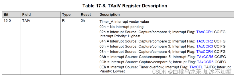
由上表可知,0Eh表示中断源为Timer overflow,因此读取TAxIV为14时会进入对应的中断处理程序。
// void config_blue_pwm(void)中添加:// Enable the overflow interruptTIMER_A2->CTL &= ~TIMER_A_CTL_IFG;NVIC_EnableIRQ (TA2_N_IRQn);TIMER_A2->CTL |= TIMER_A_CTL_IE;
// void config_red_green_pwm(void)中添加:// Enable the overflow interruptTIMER_A0->CTL &= ~TIMER_A_CTL_IFG;NVIC_EnableIRQ (TA0_N_IRQn);TIMER_A0->CTL |= TIMER_A_CTL_IE;
static uint8_t new_duty_red = 0;
static uint8_t new_duty_green = 0;
static uint8_t new_duty_blue = 0;
static uint8_t need_to_change_r = 0;
static uint8_t need_to_change_g = 0;
static uint8_t need_to_change_b = 0;/*** configure the blue led to be controlled by PWM.* Parameters: the duty to control the lightness* Return value: run successfully or not. if the duty is out of range from 5% to 95%, return 1. otherwise, return 0.*/
uint8_t pwm_blue (uint8_t duty){if((duty < 0) || (duty > 100)) {TIMER_A2->CCTL[1] &= ~(TIMER_A_CCTLN_OUTMOD_MASK);TIMER_A2->CCTL[1] &= ~TIMER_A_CCTLN_OUT;need_to_change_b = 0;return 1;} else if(duty < 5) {TIMER_A2->CCTL[1] &= ~(TIMER_A_CCTLN_OUTMOD_MASK);TIMER_A2->CCTL[1] &= ~TIMER_A_CCTLN_OUT;need_to_change_b = 0;} else if(duty > 95) {TIMER_A2->CCTL[1] &= ~(TIMER_A_CCTLN_OUTMOD_MASK);TIMER_A2->CCTL[1] |= TIMER_A_CCTLN_OUT;need_to_change_b = 0;} else {new_duty_blue = duty;need_to_change_b = 1;}//printf("blue: %d\n", duty);return 0;
}/*** configure the red led to be controlled by PWM.* Parameters: the duty to control the lightness* Return value: run successfully or not. if the duty is out of range from 5% to 95%, return 1. otherwise, return 0.*/
uint8_t pwm_red (uint8_t duty){if((duty < 0) || (duty > 100)) {TIMER_A0->CCTL[3] &= ~(TIMER_A_CCTLN_OUTMOD_MASK);TIMER_A0->CCTL[3] &= ~TIMER_A_CCTLN_OUT;need_to_change_r = 0;return 1;} else if(duty < 5) {TIMER_A0->CCTL[3] &= ~(TIMER_A_CCTLN_OUTMOD_MASK);TIMER_A0->CCTL[3] &= ~TIMER_A_CCTLN_OUT;need_to_change_r = 0;} else if(duty > 95) {TIMER_A0->CCTL[3] &= ~(TIMER_A_CCTLN_OUTMOD_MASK);TIMER_A0->CCTL[3] |= TIMER_A_CCTLN_OUT;need_to_change_r = 0;} else {new_duty_red = duty;need_to_change_r = 1;}//printf("red: %d\n", duty);return 0;
}/*** configure the green led to be controlled by PWM.* Parameters: the duty to control the lightness* Return value: run successfully or not. if the duty is out of range from 5% to 95%, return 1. otherwise, return 0.*/
uint8_t pwm_green (uint8_t duty){if((duty < 0) || (duty > 100)) {TIMER_A0->CCTL[1] &= ~TIMER_A_CCTLN_OUT;TIMER_A0->CCTL[1] &= ~(TIMER_A_CCTLN_OUTMOD_MASK);need_to_change_g = 0;return 1;} else if(duty < 5) {TIMER_A0->CCTL[1] &= ~TIMER_A_CCTLN_OUT;TIMER_A0->CCTL[1] &= ~(TIMER_A_CCTLN_OUTMOD_MASK);need_to_change_g = 0;} else if(duty > 95) {TIMER_A0->CCTL[1] |= TIMER_A_CCTLN_OUT;TIMER_A0->CCTL[1] &= ~(TIMER_A_CCTLN_OUTMOD_MASK);need_to_change_g = 0;} else {new_duty_green = duty;need_to_change_g = 1;}//printf("green: %d\n", duty);return 0;
}/** ISR to handle the interrupt on TIMER_A2. (use PxIV)* Parameters: none.* Return value: none.*/
void TA2_N_IRQHandler(void){switch (TIMER_A2->IV){case 14:// blueif (need_to_change_b == 1){TIMER_A2->CCR[1] = TIMER_A2->CCR[0] * new_duty_blue / 100;TIMER_A2->CCTL[1] |= TIMER_A_CCTLN_OUTMOD_7;need_to_change_b = 0;}break;default:{}break;}
}/** ISR to handle the interrupt on TIMER_A0. (use PxIV)* Parameters: none.* Return value: none.*/
void TA0_N_IRQHandler(void){switch (TIMER_A0->IV){case 14:if (need_to_change_r == 1){// redTIMER_A0->CCR[3] = TIMER_A0->CCR[0] * new_duty_red / 100;TIMER_A0->CCTL[3] |= TIMER_A_CCTLN_OUTMOD_7;need_to_change_r = 0;}if (need_to_change_g == 1){// greenTIMER_A0->CCR[1] = TIMER_A0->CCR[0] * new_duty_green / 100;TIMER_A0->CCTL[1] |= TIMER_A_CCTLN_OUTMOD_7;need_to_change_g = 0;}break;default:{}break;}
}
6.8 最终主函数
#include <stdint.h>
#include <stdio.h>
#include "msp.h"
#include "game.h"
#include "buttons.h"
#include "led_control.h"
#include "analog.h"
#include "timer.h"/*** main.c*/
void main(void)
{// Declaration of variablesuint8_t menu, menu_option, game, error;uint16_t xx = 0, yy = 0, time = 0;int v_speed = 0, v_wheel = 0;WDT_A->CTL = WDT_A_CTL_PW | WDT_A_CTL_HOLD;   // Stop WDT// Enable global interrupt and initialize_enable_interrupts();Init_Game(); //Requires interruptsinit_buttons_int();//init_rgb(); // use the led with GPIOinit_adc14();config_joystic();config_pwm(); // use the led with PWMwhile (1)  //Super Loop{led_off_pwm();Create_Menu();menu = 1;  // The menu is runningtime = 0;while (menu){error = Show_Menu(menu_option);if (error){show_error("PARAM", "ERROR");}if (check_and_clear_any_button_flag(BUTTON_BOTTOM) == 1) // Go down the menu if bottom button is pressed{menu_option = (menu_option + 1) % 3; // Add 1 to menu_option taking care that there are 3 options}if (check_and_clear_any_button_flag(BUTTON_UPPER) == 1) // Choose the color if the upper button is pressed{if((menu_option < 0) || (menu_option > 2)) { show_error("COLOR", "ERROR"); } // Check the correctness of the parameter.Set_Car_Color(menu_option); // Call library function Set_Car_Color.//led_on(menu_option);led_on_pwm(menu_option, 25);}if (check_and_clear_any_button_flag(BUTTON_JOYSTICK) == 1) // End menu loop and go to next loop if joystick button is pressed{if((menu_option < 0) || (menu_option > 2)) { show_error("COLOR", "ERROR"); } // Check the correctness of the menu_option.menu = 0; // End the menu loop}}led_off_pwm();Init_Game ();game = 1; // Let's play!!!while (game){if (check_SysTick_flag()) // SysTick event every 40ms{Draw_Road();Draw_Car();if (read_button_bottom() == 1) // Update speed if bottom button is pressed{change_speed(-1); // Call library function to decrease speed one unit}if (read_button_upper() == 1) // Update speed if upper button is pressed{change_speed(1); // Call library function to increase speed one unit}if (check_and_clear_any_button_flag(BUTTON_JOYSTICK) == 1) // End game loop if joystick button is pressed{game = 0; // End the game loop}read_joystick(&xx, &yy);v_speed = yy / 3277 - 2; // divide the speed into five levels: [-2, 2]if((v_speed < -2) || (v_speed > 2)) { show_error("JOYSICK", "ERROR"); } // Check the correctness of v_speedchange_speed(v_speed*3); // change the speed according to the level. (-6 -3 0 +3 +6)v_wheel = (xx - 470) / 3183 - 2; // divide the wheel into five levels: [-2, 2]if((v_wheel < -2) || (v_wheel > 2)) { show_error("JOYSICK", "ERROR"); } // Check the correctness of v_wheelSteering_Wheel(v_wheel); // change the wheel according to the level. (-2 -1 0 +1 +2)//printf("xx: %d, yy: %d, v_speed: %d, v_wheel: %d\n", xx, yy, v_speed*3, v_wheel);//加速减速修改颜色//游戏时长增加亮度if(v_speed > 0){led_on_pwm(1, (time % 3600) / 40 + 5);}if(v_speed == 0){led_on_pwm(2, (time % 3600) / 40 + 5);}if(v_speed < 0){led_on_pwm(0, (time % 3600) / 40 + 5);}time = time + 1;}}}
}
七 其他
- <>头文件:在编译器安装目录的标准库中查找;""头文件:在源程序文件夹中查找。
- 尽量使用msp432p401r.h中的位名和域名,而非直接使用数。在某些情况下局部修改不会为其他区域清0,可能会造成结果错误。
- 要设置想要转换的通道,可能要使用字段偏移和掩码。
- 字段偏移示例
#define ADC14_CTL1_CSTARTADD_OFS (16) /*!< ADC14CSTARTADD Bit Offset */ // Set 8 as channel start ADC14->CTL1 |= (8 << ADC14_CTL1_CSTARTADD_OFS); - 掩码示例
#define ADC14_CTL1_CSTARTADD_MASK ((uint32_t)0x001F0000) /*!< ADC14CSTARTADD Bit Mask */
//Returns the actual channel start
channel = (ADC14->CTL1 & ADC14_CTL1_CSTARTADD_MASK) >> ADC14_CTL1_CSTARTADD_OFS;
- 字段偏移示例
这篇关于MSP-EXP432实践项目 小车游戏的文章就介绍到这儿,希望我们推荐的文章对编程师们有所帮助!


