本文主要是介绍Verilog学习笔记HDLBits——Arithmetic Circuits,希望对大家解决编程问题提供一定的参考价值,需要的开发者们随着小编来一起学习吧!
提示:文章写完后,目录可以自动生成,如何生成可参考右边的帮助文档
文章目录
- 前言
- 一、Arithmetic Circuits
- 1. Half adder
- 2. Full adder
- 3. 3-bit binary adder
- 4. Adder
- 5. Signed addition overflow
- 6. 100-bit binary adder
- 7. 4-digit BCD adder
- 总结
前言
加法器:
加法器是产生数的和的装置。加数和被加数为输入,和数与进位为输出的装置为半加器。若加数、被加数与低位的进位数为输入,而和数与进位为输出则为全加器。常用作计算机算术逻辑部件,执行逻辑操作、移位与指令调用。
一、Arithmetic Circuits
1. Half adder
Practice:Create a half adder. A half adder adds two bits (with no carry-in) and produces a sum and carry-out.
翻译:创建半加法器。半加法器将两个位相加(不带进项),产生一个总数和进位。
Solution(不唯一,仅供参考):
module top_module( input a, b,output cout, sum );assign {cout,sum} = a+b;
endmodule
2. Full adder
Practice:Create a full adder. A full adder adds three bits (including carry-in) and produces a sum and carry-out.
翻译:创建完整的加法器。一个完整的加法器加3位(包括进位),产生一个总数和进位。
Solution(不唯一,仅供参考):
module top_module( input a, b, cin,output cout, sum );assign {cout,sum} = a+b+cin;
endmodule
方法二
module top_module( input a, b, cin,output cout, sum );assign cout = a&b | a&cin | b&cin;assign sum = a^b^cin;
endmodule
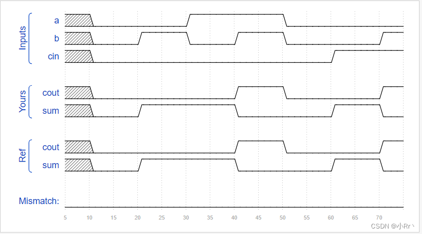
Timing Diagram
3. 3-bit binary adder
Practice:Now that you know how to build a full adder, make 3 instances of it to create a 3-bit binary ripple-carry adder. The adder adds two 3-bit numbers and a carry-in to produce a 3-bit sum and carry out. To encourage you to actually instantiate full adders, also output the carry-out from each full adder in the ripple-carry adder. cout[2] is the final carry-out from the last full adder, and is the carry-out you usually see.
翻译:本题中需要通过实例化 3 个全加器,并将它们级联起来实现一个位宽为 3 bit 的二进制加法器。
Solution(不唯一,仅供参考):
module top_module( input [2:0] a, b,input cin,output [2:0] cout,output [2:0] sum );add add0(.a(a[0]), .b(b[0]), .cin(cin), .cout(cout[0]), .sum(sum[0]));add add1(.a(a[1]), .b(b[1]), .cin(cout[0]), .cout(cout[1]), .sum(sum[1]));add add2(.a(a[2]), .b(b[2]), .cin(cout[1]), .cout(cout[2]), .sum(sum[2]));
endmodulemodule add(input a,b,input cin,output cout,sum
);assign {cout,sum} = a+b+cin;
endmodule
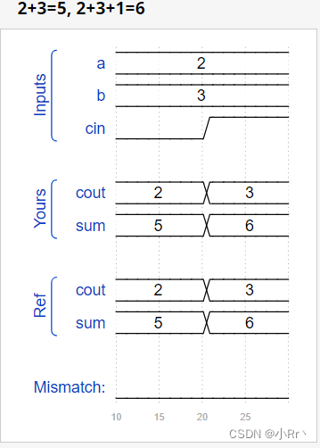
Timing Diagram
4. Adder
Practice:Implement the following circuit:
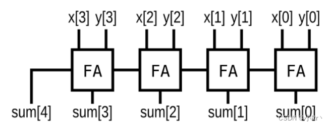
翻译:实现电路图上的电路,创建一个全家器。
Solution(不唯一,仅供参考):
module top_module (input [3:0] x,input [3:0] y, output [4:0] sum);assign sum =x+y;
endmodule
也可以用上题的实例化进行求解,verilog 的语法会自动将 x+y 扩展成 5 bit 数。
5. Signed addition overflow
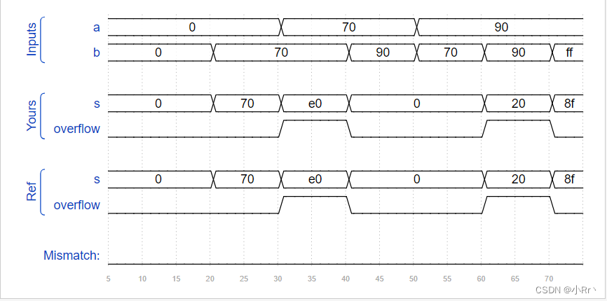
Practice:Assume that you have two 8-bit 2’s complement numbers, a[7:0] and b[7:0]. These numbers are added to produce s[7:0]. Also compute whether a (signed) overflow has occurred.
翻译:假设有两个8位的2的补数,a[7:0]和b[7:0]。这些数字相加得到s[7:0]。再判断是否发生了(带符号的)溢出。
提示:当两个正数相加产生负数,或者两个负数相加产生正数时,就会发生带符号溢出。有几种检测溢出的方法:可以通过比较输入和输出数字的符号来计算溢出,也可以从位n和n-1的进位导出溢出。
Solution(不唯一,仅供参考):
module top_module (input [7:0] a,input [7:0] b,output [7:0] s,output overflow
); //当两个正数相加产生负数,或者两个负数相加产生正数时,就会发生带符号溢出assign s = a+b;assign overflow = (a[7]&b[7]&~s[7])|(~a[7]&~b[7]&s[7]);
endmodule
方法二
module top_module (input [7:0] a,input [7:0] b,output [7:0] s,output overflow
); //从位n和n-1的进位导出溢出wire [8:0] sum;assign sum = {a[7],a}+{b[7],b};assign s = sum;assign overflow = sum[8]^sum[7];endmodule
Timing Diagram:
6. 100-bit binary adder
Practice:Create a 100-bit binary adder. The adder adds two 100-bit numbers and a carry-in to produce a 100-bit sum and carry out.
翻译:创建一个100位二进制加法器。
Solution(不唯一,仅供参考):
module top_module( input [99:0] a, b,input cin,output cout,output [99:0] sum );assign {cout,sum} = a+b+cin;
endmodule
7. 4-digit BCD adder
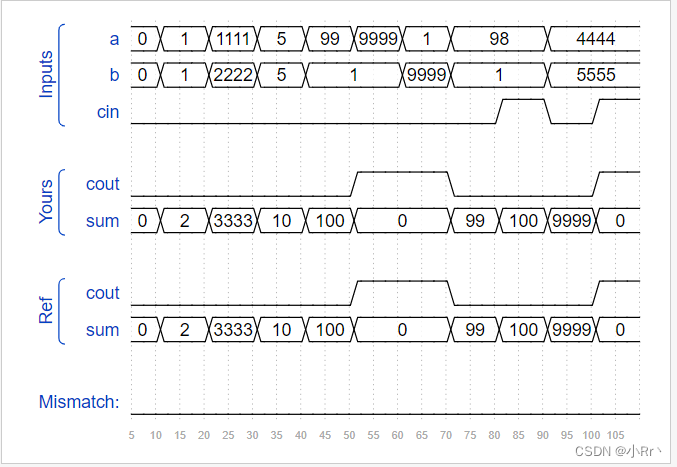
Practice:Instantiate 4 copies of bcd_fadd to create a 4-digit BCD ripple-carry adder. Your adder should add two 4-digit BCD numbers (packed into 16-bit vectors) and a carry-in to produce a 4-digit sum and carry out.
翻译:实例化4个bcd_fadd副本,创建4位BCD进位加法器。你的加法器应该将两个4位的BCD数字(打包成16位向量)和一个进位相加,得到4位的和并进位。
Solution(不唯一,仅供参考):
module top_module ( input [15:0] a, b,input cin,output cout,output [15:0] sum );wire [3:0] cout0;bcd_fadd bcd_fadd0(.a(a[3:0]),.b(b[3:0]),.cin(cin),.cout(cout0[0]),.sum(sum[3:0]));bcd_fadd bcd_fadd1(.a(a[7:4]),.b(b[7:4]),.cin(cout0[0]),.cout(cout0[1]),.sum(sum[7:4]));bcd_fadd bcd_fadd2(.a(a[11:8]),.b(b[11:8]),.cin(cout0[1]),.cout(cout0[2]),.sum(sum[11:8]));bcd_fadd bcd_fadd3(.a(a[15:12]),.b(b[15:12]),.cin(cout0[2]),.cout(cout0[3]),.sum(sum[15:12]));  assign cout = cout0[3];
endmodule
方法二
module top_module( input [15:0] a, b,input cin,output cout,output [15:0] sum );wire [4:0] cout0;assign cout0[0] = cin;genvar i;generatefor(i=0;i<4;i=i+1)begin:add16bcd_fadd bcd_fadd_i(a[4*i+:4],b[4*i+:4],cout0[i],cout16[i+1],sum[4*i+:4]);endendgenerateassign cout = cout0[4];endmodule
Timing Diagram
总结
1、 加法器的逻辑关系:
sum = a^b^cin;
cout = a&b | a&cin | b&cin;
继续加油!!!!!
这篇关于Verilog学习笔记HDLBits——Arithmetic Circuits的文章就介绍到这儿,希望我们推荐的文章对编程师们有所帮助!


