本文主要是介绍FSMC读取FPGA的FIFO,希望对大家解决编程问题提供一定的参考价值,需要的开发者们随着小编来一起学习吧!
一、硬件说明
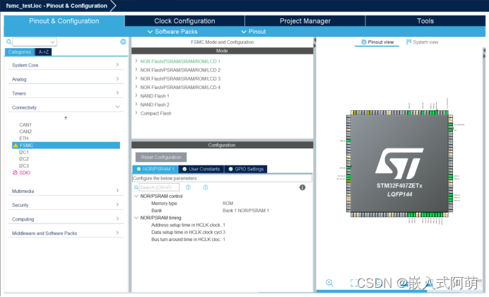
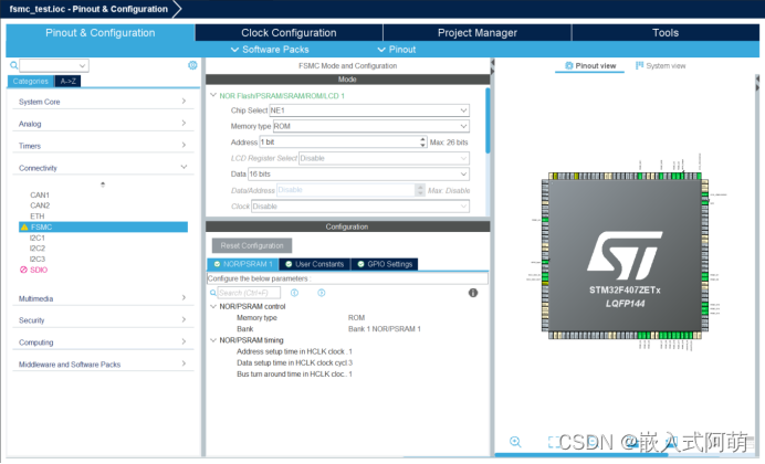
- FSMC配置


单片机的代码如下:
#define VALUE_ADDRESS_AD1 (__IO uint16_t *)0x60400000while (1){if(!HAL_GPIO_ReadPin(GPIOF, GPIO_PIN_8)) //数据非空{data = *(__IO uint16_t *)VALUE_ADDRESS_AD1;data2 = *(__IO uint16_t *)VALUE_ADDRESS_AD1;printf("fsmc rd %d:%d\r\n",data,data2);HAL_Delay(10);}}
- FPGA代码
//
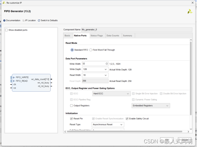
// Description: 数据传入32位的FIFO, 用FSMC分2次读出
//
module fifo_32_fsmc_rd(input clk,input reset_n,input fsmc_noe, //read signaloutput led,output  fifo_empty,output reg [15:0]fsmc_data);
parameter  WR_CNT = 5'd30-1;//写入30组数据wire   empty;
assign  fifo_empty = empty;
assign  led =!empty; //fifo有数据则灯亮,空则灭    assign rst = !reset_n;
//先往FIFO存入数据
wire  wr_rst_busy;
reg [4:0]wr_cnt;//写入的数据进行计数
reg [3:0]state; //4种状态
parameter  IDLE = 4'b0001,READY =4'b0010,WRITE =4'b0100;
always @(posedge clk or negedge reset_n)beginif(!reset_n)state<=IDLE; //空闲状态else case(state)IDLE:if(wr_rst_busy)state<=IDLE;elsestate<=READY; //ready状态READY:if(wr_rst_busy)state<=IDLE;else if(empty)//若空则写入数据state<=WRITE;elsestate<=READY;WRITE:if(wr_cnt < WR_CNT)state <= WRITE;else state <= READY;default:  state<=IDLE;                     endcase
end
reg  wr_en;
always @(posedge clk or negedge reset_n)beginif(!reset_n)beginwr_cnt <= 5'd0;wr_en <= 1'b0;endelse if(state == WRITE)beginwr_en <= 1'b1;wr_cnt <= wr_cnt+1'b1;endelse if(state == READY)beginwr_cnt <= 5'd0;wr_en <= 1'b0;end
endreg [31:0]din ;//fifo输入数据累加
always @(posedge clk or negedge reset_n)beginif(!reset_n)din <=32'd0;else if(state == WRITE)din <= din +1'b1;elsedin <= din ;
end   //从FIFO开始往外读出
wire [7:0]wr_data_count;//fsmc_noe下降沿检测
reg reg_fsmc_noe1;
reg reg_fsmc_noe2;
wire  falling_fsmc_noe;always @(posedge clk)beginreg_fsmc_noe1 <= fsmc_noe;reg_fsmc_noe2 <= reg_fsmc_noe1;
end
assign falling_fsmc_noe = ((!reg_fsmc_noe1) & reg_fsmc_noe2);wire [15 : 0] dout;
wire rd_rst_busy;
always @(posedge clk )fsmc_data <= dout;fifo_generator_0 fifo_32in (.clk(clk),                      // input wire clk.rst(rst),                      // input wire rst.din(din),                      // input wire [31 : 0] din.wr_en(wr_en),                  // input wire wr_en.rd_en(falling_fsmc_noe),                  // input wire rd_en.dout(dout),                    // output wire [15 : 0] dout.full(),                    // output wire full.empty(empty),                  // output wire empty.wr_data_count(wr_data_count),  // output wire [7 : 0] wr_data_count.wr_rst_busy(wr_rst_busy),      // output wire wr_rst_busy.rd_rst_busy(rd_rst_busy)      // output wire rd_rst_busy
);  endmodule
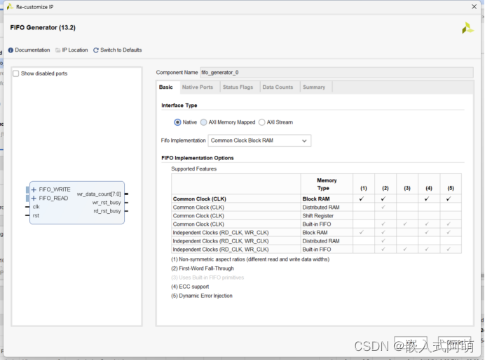
配置FIFO


写FIFO测试
`timescale 1ns / 1psmodule fifo_32_fsmc_rd_tb();
reg clk,noe,reset_n;
wire fifo_empty;initial clk=1'b1;
always #10 clk= ~clk;initial beginreset_n = 1'b0;noe=1;#51;reset_n = 1'b1;#10000;$stop;
endfifo_32_fsmc_rd fifo_32_fsmc_rd1(.clk(clk),.reset_n(reset_n),.fsmc_noe(noe), //read signal.led(),.fifo_empty(fifo_empty),.fsmc_data());
endmodule
2. 最终单片机读到数据的实验结果, 只截取部分数据
smc rd 0:88
fsmc rd 0:89
fsmc rd 0:90
fsmc rd 0:91
fsmc rd 0:92
fsmc rd 0:93
fsmc rd 0:94
fsmc rd 0:95
fsmc rd 0:96
fsmc rd 0:97
fsmc rd 0:98
fsmc rd 0:99
fsmc rd 0:100
fsmc rd 0:101
fsmc rd 0:102
fsmc rd 0:103
fsmc rd 0:104
fsmc rd 0:105
fsmc rd 0:106
fsmc rd 0:107
fsmc rd 0:108
fsmc rd 0:109
fsmc rd 0:110
fsmc rd 0:111
fsmc rd 0:112
fsmc rd 0:113
fsmc rd 0:114
fsmc rd 0:115
fsmc rd 0:116
fsmc rd 0:117
fsmc rd 0:118
fsmc rd 0:119
fsmc rd 0:120
fsmc rd 0:121
fsmc rd 0:122
fsmc rd 0:123
fsmc rd 0:124
fsmc rd 0:125
fsmc rd 0:126
fsmc rd 0:127
fsmc rd 0:128
fsmc rd 0:129
fsmc rd 0:130
读出的数据正常
这篇关于FSMC读取FPGA的FIFO的文章就介绍到这儿,希望我们推荐的文章对编程师们有所帮助!


