本文主要是介绍ZYNQ EMIO MIO,希望对大家解决编程问题提供一定的参考价值,需要的开发者们随着小编来一起学习吧!
1 概述
先来了解GPIO的BANK分布,在UG585文档GPIO一章中可以看到GPIO是有4个BANK,
注意与MIO的BANK区分。
BANK0 控制32个信号,BANK1控制22个信号,总共是MIO的54个引脚,也就是诸如
SPI,I2C,USB,SD 等 PS 端外设接口;
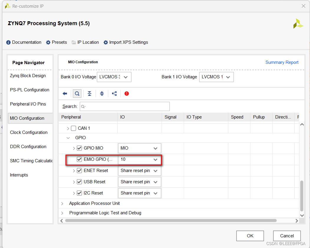
BANK2和BANK3共能控制64个PL端引脚,注意每一组都有三个信号,输入EMIOGPIOI,
输出EMIOGPIOO,输出使能EMIOGPIOTN,类似于三态门,共192个信号。可以连接到PL
端引脚,通过PS控制信号。

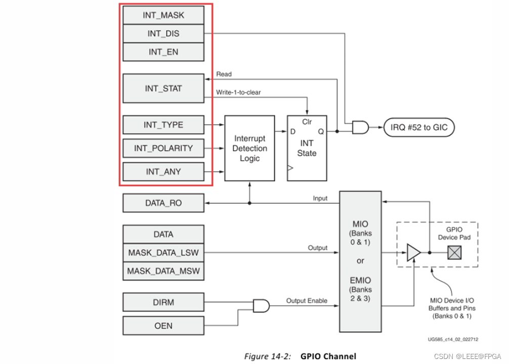
下图为GPIO的控制框图,实验中会用到输出部分的寄存器,数据寄存器DATA,数据掩
码寄存器MASK_DATA_LSW,MASK_DATA_MSW,方向控制寄存器DIRM,输出使能控制
器OEN。


2 MIO 按键中断
前面介绍了MIO作为输出控制LED灯,这里讲一下利用MIO作为按键输入控制LED灯。
- 通过UG585文档看下GPIO的结构图,中断的寄存器:
INT_MASK:中断掩码
INT_DIS: 中断关闭
INT_EN: 中断使能
INT_TYPE: 中断类型,设置电平敏感还是边沿敏感
INT_POLARITY: 中断极性,设置低电平或下降沿还是高电平或上升沿
INT_ANY: 边沿触发方式,需要INT_TYPE设置为边沿敏感才能使用
设置中断产生方式时需要INT_TYPE、INT_POLARITY、INT_ANY配合使用。具体寄存器含义请参
考UG585 Register Details 部分。

/******************************************************************************
*
* Copyright (C) 2009 - 2014 Xilinx, Inc.  All rights reserved.
*
* Permission is hereby granted, free of charge, to any person obtaining a copy
* of this software and associated documentation files (the "Software"), to deal
* in the Software without restriction, including without limitation the rights
* to use, copy, modify, merge, publish, distribute, sublicense, and/or sell
* copies of the Software, and to permit persons to whom the Software is
* furnished to do so, subject to the following conditions:
*
* The above copyright notice and this permission notice shall be included in
* all copies or substantial portions of the Software.
*
* Use of the Software is limited solely to applications:
* (a) running on a Xilinx device, or
* (b) that interact with a Xilinx device through a bus or interconnect.
*
* THE SOFTWARE IS PROVIDED "AS IS", WITHOUT WARRANTY OF ANY KIND, EXPRESS OR
* IMPLIED, INCLUDING BUT NOT LIMITED TO THE WARRANTIES OF MERCHANTABILITY,
* FITNESS FOR A PARTICULAR PURPOSE AND NONINFRINGEMENT. IN NO EVENT SHALL
* XILINX  BE LIABLE FOR ANY CLAIM, DAMAGES OR OTHER LIABILITY,
* WHETHER IN AN ACTION OF CONTRACT, TORT OR OTHERWISE, ARISING FROM, OUT OF
* OR IN CONNECTION WITH THE SOFTWARE OR THE USE OR OTHER DEALINGS IN THE
* SOFTWARE.
*
* Except as contained in this notice, the name of the Xilinx shall not be used
* in advertising or otherwise to promote the sale, use or other dealings in
* this Software without prior written authorization from Xilinx.
*
******************************************************************************//** helloworld.c: simple test application** This application configures UART 16550 to baud rate 9600.* PS7 UART (Zynq) is not initialized by this application, since* bootrom/bsp configures it to baud rate 115200** ------------------------------------------------* | UART TYPE   BAUD RATE                        |* ------------------------------------------------*   uartns550   9600*   uartlite    Configurable only in HW design*   ps7_uart    115200 (configured by bootrom/bsp)*/#include <stdio.h>
#include "platform.h"
#include "xil_printf.h"
#include "sleep.h"
#include "xgpiops.h"#define GPIO_DEVICE_ID		XPAR_XGPIOPS_0_DEVICE_ID/** The following are declared globally so they are zeroed and can be* easily accessible from a debugger.*/
XGpioPs Gpio;	/* The driver instance for GPIO Device. */int main()
{init_platform();int Status;XGpioPs_Config *ConfigPtr;/* Initialize the GPIO driver. */ConfigPtr = XGpioPs_LookupConfig(GPIO_DEVICE_ID);Status = XGpioPs_CfgInitialize(&Gpio, ConfigPtr,ConfigPtr->BaseAddr);if (Status != XST_SUCCESS) {return XST_FAILURE;}/** Set the direction for the pin to be output and* Enable the Output enable for the LED Pin.*/XGpioPs_SetDirectionPin(&Gpio, 54, 1);XGpioPs_SetDirectionPin(&Gpio, 55, 1);XGpioPs_SetDirectionPin(&Gpio, 56, 1);XGpioPs_SetDirectionPin(&Gpio, 57, 1);XGpioPs_SetDirectionPin(&Gpio, 58, 1);XGpioPs_SetDirectionPin(&Gpio, 59, 1);XGpioPs_SetDirectionPin(&Gpio, 60, 1);XGpioPs_SetDirectionPin(&Gpio, 61, 1);XGpioPs_SetDirectionPin(&Gpio, 62, 1);XGpioPs_SetDirectionPin(&Gpio, 63, 1);XGpioPs_SetOutputEnablePin(&Gpio, 54, 1);XGpioPs_SetOutputEnablePin(&Gpio, 55, 1);XGpioPs_SetOutputEnablePin(&Gpio, 56, 1);XGpioPs_SetOutputEnablePin(&Gpio, 57, 1);XGpioPs_SetOutputEnablePin(&Gpio, 58, 1);XGpioPs_SetOutputEnablePin(&Gpio, 59, 1);XGpioPs_SetOutputEnablePin(&Gpio, 60, 1);XGpioPs_SetOutputEnablePin(&Gpio, 61, 1);XGpioPs_SetOutputEnablePin(&Gpio, 62, 1);XGpioPs_SetOutputEnablePin(&Gpio, 63, 1);while(1){/* Set the GPIO output to be low. */XGpioPs_WritePin(&Gpio, 54, 0x0);XGpioPs_WritePin(&Gpio, 55, 0x0);XGpioPs_WritePin(&Gpio, 56, 0x0);XGpioPs_WritePin(&Gpio, 57, 0x0);XGpioPs_WritePin(&Gpio, 58, 0x0);XGpioPs_WritePin(&Gpio, 59, 0x0);XGpioPs_WritePin(&Gpio, 60, 0x0);XGpioPs_WritePin(&Gpio, 61, 0x0);XGpioPs_WritePin(&Gpio, 62, 0x0);XGpioPs_WritePin(&Gpio, 63, 0x0);sleep(1);print("Hello World\n\r");/* Set the GPIO output to be high. */XGpioPs_WritePin(&Gpio, 54, 0x1);XGpioPs_WritePin(&Gpio, 55, 0x1);XGpioPs_WritePin(&Gpio, 56, 0x1);XGpioPs_WritePin(&Gpio, 57, 0x1);XGpioPs_WritePin(&Gpio, 58, 0x1);XGpioPs_WritePin(&Gpio, 59, 0x1);XGpioPs_WritePin(&Gpio, 60, 0x1);XGpioPs_WritePin(&Gpio, 61, 0x1);XGpioPs_WritePin(&Gpio, 62, 0x1);XGpioPs_WritePin(&Gpio, 63, 0x1);sleep(1);}cleanup_platform();return 0;
}
带按键中断的代码
/******************************************************************************
*
* Copyright (C) 2009 - 2014 Xilinx, Inc.  All rights reserved.
*
* Permission is hereby granted, free of charge, to any person obtaining a copy
* of this software and associated documentation files (the "Software"), to deal
* in the Software without restriction, including without limitation the rights
* to use, copy, modify, merge, publish, distribute, sublicense, and/or sell
* copies of the Software, and to permit persons to whom the Software is
* furnished to do so, subject to the following conditions:
*
* The above copyright notice and this permission notice shall be included in
* all copies or substantial portions of the Software.
*
* Use of the Software is limited solely to applications:
* (a) running on a Xilinx device, or
* (b) that interact with a Xilinx device through a bus or interconnect.
*
* THE SOFTWARE IS PROVIDED "AS IS", WITHOUT WARRANTY OF ANY KIND, EXPRESS OR
* IMPLIED, INCLUDING BUT NOT LIMITED TO THE WARRANTIES OF MERCHANTABILITY,
* FITNESS FOR A PARTICULAR PURPOSE AND NONINFRINGEMENT. IN NO EVENT SHALL
* XILINX  BE LIABLE FOR ANY CLAIM, DAMAGES OR OTHER LIABILITY,
* WHETHER IN AN ACTION OF CONTRACT, TORT OR OTHERWISE, ARISING FROM, OUT OF
* OR IN CONNECTION WITH THE SOFTWARE OR THE USE OR OTHER DEALINGS IN THE
* SOFTWARE.
*
* Except as contained in this notice, the name of the Xilinx shall not be used
* in advertising or otherwise to promote the sale, use or other dealings in
* this Software without prior written authorization from Xilinx.
*
******************************************************************************//** helloworld.c: simple test application** This application configures UART 16550 to baud rate 9600.* PS7 UART (Zynq) is not initialized by this application, since* bootrom/bsp configures it to baud rate 115200** ------------------------------------------------* | UART TYPE   BAUD RATE                        |* ------------------------------------------------*   uartns550   9600*   uartlite    Configurable only in HW design*   ps7_uart    115200 (configured by bootrom/bsp)*/#include <stdio.h>
#include "platform.h"
#include "xscugic.h"
#include "xil_printf.h"
#include "sleep.h"
#include "xgpiops.h"#define GPIO_DEVICE_ID		XPAR_XGPIOPS_0_DEVICE_ID
#define INTC_DEVICE_ID	    XPAR_SCUGIC_SINGLE_DEVICE_ID
#define KEY_INTR_ID         XPAR_XGPIOPS_0_INTR#define EMIO_LD0  58
#define EMIO_LD1  59
#define EMIO_LD2  60
#define EMIO_LD3  61/** The following are declared globally so they are zeroed and can be* easily accessible from a debugger.*/
XGpioPs Gpio;	/* The driver instance for GPIO Device. */
int key_flag ;
XScuGic INTCInst;int IntrInitFuntion(XScuGic *InstancePtr, u16 DeviceId, XGpioPs *GpioInstancePtr);
void GpioHandler(void *CallbackRef);int main()
{init_platform();int Status;XGpioPs_Config *ConfigPtr;int key_val  = 0 ;key_flag = 0 ;/* Initialize the GPIO driver. */ConfigPtr = XGpioPs_LookupConfig(GPIO_DEVICE_ID);Status = XGpioPs_CfgInitialize(&Gpio, ConfigPtr,ConfigPtr->BaseAddr);if (Status != XST_SUCCESS) {return XST_FAILURE;}/** Set the direction for the pin to be output and* Enable the Output enable for the LED Pin.*/XGpioPs_SetDirectionPin(&Gpio, 54, 1);XGpioPs_SetDirectionPin(&Gpio, 55, 1);XGpioPs_SetDirectionPin(&Gpio, 56, 1);XGpioPs_SetDirectionPin(&Gpio, 57, 1);XGpioPs_SetDirectionPin(&Gpio, 58, 1);XGpioPs_SetDirectionPin(&Gpio, 59, 1);XGpioPs_SetDirectionPin(&Gpio, 60, 1);XGpioPs_SetDirectionPin(&Gpio, 61, 1);XGpioPs_SetDirectionPin(&Gpio, 62, 1);XGpioPs_SetDirectionPin(&Gpio, 63, 1);XGpioPs_SetOutputEnablePin(&Gpio, 54, 1);XGpioPs_SetOutputEnablePin(&Gpio, 55, 1);XGpioPs_SetOutputEnablePin(&Gpio, 56, 1);XGpioPs_SetOutputEnablePin(&Gpio, 57, 1);XGpioPs_SetOutputEnablePin(&Gpio, 58, 1);XGpioPs_SetOutputEnablePin(&Gpio, 59, 1);XGpioPs_SetOutputEnablePin(&Gpio, 60, 1);XGpioPs_SetOutputEnablePin(&Gpio, 61, 1);XGpioPs_SetOutputEnablePin(&Gpio, 62, 1);XGpioPs_SetOutputEnablePin(&Gpio, 63, 1);//KEY/** Set the direction for the pin to be input.* Set interrupt type as rising edge and enable gpio interrupt*/XGpioPs_SetDirectionPin(&Gpio, 64, 0);XGpioPs_SetIntrTypePin(&Gpio, 64, XGPIOPS_IRQ_TYPE_EDGE_RISING) ;XGpioPs_IntrEnablePin(&Gpio, 64) ;XGpioPs_SetDirectionPin(&Gpio, 65, 0);XGpioPs_SetDirectionPin(&Gpio, 66, 0);XGpioPs_SetDirectionPin(&Gpio, 67, 0);//SWXGpioPs_SetDirectionPin(&Gpio, 68, 0);XGpioPs_SetDirectionPin(&Gpio, 69, 0);/** sets up the interrupt system*/Status = IntrInitFuntion(&INTCInst, 64, &Gpio) ;if (Status != XST_SUCCESS)return XST_FAILURE ;while(1){/* Set the GPIO output to be low. */XGpioPs_WritePin(&Gpio, 54, 0x0);XGpioPs_WritePin(&Gpio, 55, 0x0);XGpioPs_WritePin(&Gpio, 56, 0x0);XGpioPs_WritePin(&Gpio, 57, 0x0);XGpioPs_WritePin(&Gpio, 58, 0x0);XGpioPs_WritePin(&Gpio, 59, 0x0);XGpioPs_WritePin(&Gpio, 60, XGpioPs_ReadPin(&Gpio,68));XGpioPs_WritePin(&Gpio, 61, XGpioPs_ReadPin(&Gpio,69));//XGpioPs_WritePin(&Gpio, 62, 0x0);XGpioPs_WritePin(&Gpio, 63, 0x0);if (key_flag){XGpioPs_WritePin(&Gpio, 62, key_val) ;key_val = ~key_val ;key_flag = 0 ;}sleep(1);print("Hello World\n\r");/* Set the GPIO output to be high. */XGpioPs_WritePin(&Gpio, 54, 0x1);XGpioPs_WritePin(&Gpio, 55, 0x1);XGpioPs_WritePin(&Gpio, 56, 0x1);XGpioPs_WritePin(&Gpio, 57, 0x1);XGpioPs_WritePin(&Gpio, 58, 0x1);XGpioPs_WritePin(&Gpio, 59, 0x1);//XGpioPs_WritePin(&Gpio, 60, 0x1);//XGpioPs_WritePin(&Gpio, 61, 0x1);//XGpioPs_WritePin(&Gpio, 62, 0x1);XGpioPs_WritePin(&Gpio, 63, 0x1);sleep(1);}cleanup_platform();return 0;
}int IntrInitFuntion(XScuGic *InstancePtr, u16 DeviceId, XGpioPs *GpioInstancePtr)
{XScuGic_Config *IntcConfig;int Status ;/** Initialize the interrupt controller driver so that it is ready to* use.*/IntcConfig = XScuGic_LookupConfig(INTC_DEVICE_ID);Status = XScuGic_CfgInitialize(InstancePtr, IntcConfig, IntcConfig->CpuBaseAddress) ;if (Status != XST_SUCCESS)return XST_FAILURE ;/** set priority and trigger type*/XScuGic_SetPriorityTriggerType(InstancePtr, KEY_INTR_ID,0xA0, 0x3);/** Connect the device driver handler that will be called when an* interrupt for the device occurs, the handler defined above performs* the specific interrupt processing for the device.*/Status = XScuGic_Connect(InstancePtr, KEY_INTR_ID,(Xil_ExceptionHandler)GpioHandler,(void *)GpioInstancePtr) ;if (Status != XST_SUCCESS)return XST_FAILURE ;/** Enable the interrupt for the device.*/XScuGic_Enable(InstancePtr, KEY_INTR_ID) ;Xil_ExceptionInit();Xil_ExceptionRegisterHandler(XIL_EXCEPTION_ID_INT,(Xil_ExceptionHandler)XScuGic_InterruptHandler,InstancePtr);Xil_ExceptionEnable();return XST_SUCCESS ;}void GpioHandler(void *CallbackRef)
{XGpioPs *GpioInstancePtr = (XGpioPs *)CallbackRef ;int Int_val ;Int_val = XGpioPs_IntrGetStatusPin(GpioInstancePtr, 64) ;/** Clear interrupt.*/XGpioPs_IntrClearPin(GpioInstancePtr, 64) ;if (Int_val)key_flag = 1 ;
}
这篇关于ZYNQ EMIO MIO的文章就介绍到这儿,希望我们推荐的文章对编程师们有所帮助!


