本文主要是介绍基于Matlab的电磁场与波“电轴法”仿真,希望对大家解决编程问题提供一定的参考价值,需要的开发者们随着小编来一起学习吧!
0、代码中用到的drawEline函数
在使用代码前记得把这个函数和仿真文件放到一个文件夹下哦
function pipi=drawEline(h1,d1,d2)posAxes = get(gca, 'Position');  %获取当前坐标区位置信息
posX = posAxes(1);
posY = posAxes(2);
width = posAxes(3);
height = posAxes(4);%分解位置信息
hold on;
limX = get(gca, 'Xlim');%获取x轴范围
limY = get(gca, 'Ylim');%获取y轴范围
minX = limX(1);
maxX = limX(2);
minY = limY(1);
maxY = limY(2);
x=[h1(1).XData(d1) h1(1).XData(d2)];
y=[h1(1).YData(d1) h1(1).YData(d2)];
xNew = posX + (x - minX) / (maxX - minX) * width;
yNew = posY + (y - minY) / (maxY - minY) * height;%通过坐标变换得到箭头的绝对坐标
pipi=annotation('arrow', xNew, yNew);
1.目的:
了解电轴法的等效原理,学会用MATLAB绘制电轴法的电场线与等势面。
2.理论分析:


3.源代码与结果
3.1两根相同半径轴线(电压已知,tao未知):
3.1.1二维图源代码:
a = 3;b = 4;d = 5;u0 = 10;
e0 = 10^(-9)/(36*pi);
x = linspace(-10,10,500);
y = linspace(-10,10,500);
theta=linspace(0,2*pi,50);
xr1=b+a*cos(theta);
yr1=a*sin(theta);
xr2=-b+a*cos(theta);
yr2=a*sin(theta);
[xx, yy]=meshgrid(x, y);
tao = pi*e0*u0/(log((b+d-a)/(b-d+a)));
fai = tao*log(sqrt((xx-b).^2+yy.^2)./sqrt((xx+b).^2+yy.^2))/(2*pi*e0);
[Ex,Ey] = gradient(fai);
E = sqrt(Ex.^2+Ey.^2);
Ex = Ex./E;Ey = Ey./E;
cv=linspace(min(min(fai)),max(max(fai)),51);
contour(xx,yy,fai,cv,'r-');
title('\fontname{ ËÎÌå }\fontsize{11} 两半径相同电轴'),hold on
plot(xr1,yr1,'k','linewidth',2)
plot(xr2,yr2,'k','linewidth',2)
xlabel('x');ylabel('y'),hold off
th=linspace(0,2*pi,17);
x1=-b+0.01*cos(th);
y1=0.01*sin(th);
x2=b+0.01*cos(th);
y2=0.01*sin(th);
for i=1:17h1=streamline(xx,yy,-Ex,-Ey,x1(i),y1(i));  switch icase {1,2,9,16}drawEline(h1,1000,1001);case {3,15}drawEline(h1,1030,1031);case {4,14}drawEline(h1,1150,1151);case {5,13}drawEline(h1,1350,1351);                case {6,12}drawEline(h1,1650,1651);case {7,11}drawEline(h1,2700,2701);case {8,10}drawEline(h1,930,931);otherwisecontinueend
end
for i=[1,2,16]h1=streamline(xx,yy,Ex,Ey,x2(i),y2(i)); switch icase {2,16}drawEline(h1,930,929);case 1drawEline(h1,1000,999);otherwisecontinueend
endfill(xr2,yr2,'w')
fill(xr1,yr1,'w')
for i=1:17h1=streamline(xx,yy,-Ex,-Ey,x1(i),y1(i));  set(h1,'linestyle','--');switch icase {1,2,9,16}drawEline(h1,1000,1001);case {3,15}drawEline(h1,1030,1031);case {4,14}drawEline(h1,1150,1151);case {5,13}drawEline(h1,1350,1351);                case {6,12}drawEline(h1,1650,1651);case {7,11}drawEline(h1,2700,2701);case {8,10}drawEline(h1,930,931);otherwisecontinueend
end
for i=[1,2,16]h1=streamline(xx,yy,Ex,Ey,x2(i),y2(i)); set(h1,'linestyle','--');switch icase {2,16}drawEline(h1,930,929);case 1drawEline(h1,1000,999);otherwisecontinueend
end3.1.2二维图结果:
修改前

修改后

3.1.3三维图源代码:
x = linspace(-10,10,500);
y = linspace(-10,10,500);
[xx, yy]=meshgrid(x, y);
a = 3;b = 4;d = 5;u0 = 10;
e0 = 10^(-9)/(36*pi);
tao = pi*e0*u0/(log((b+d-a)/(b-d+a)));
fai = tao*log(sqrt((xx-b).^2+yy.^2)./sqrt((xx+b).^2+yy.^2))/(2*pi*e0);
[Ex,Ey] = gradient(fai);
E = sqrt(Ex.^2+Ey.^2);
Ex = Ex./E;Ey = Ey./E;
fai0 = tao*log(0.1/7.9)/(2*pi*e0);
F = linspace(-fai0,fai0,40);
surf(fai);
hold on
shading interp;subplot(2,1,1);
[c,h]=contour3(fai,F);
h1=streamslice(Ex,Ey);
set(h1,'Color',[0.1 0.9 0.8]);subplot(2,1,2);
for j=1:length(h1)ui = interp2(fai,h1(j).XData,h1(j).YData);h1(j).ZData = ui;
end
[c,h]=contour3(fai,F);
h.EdgeColor='k';
h.LineStyle='--';
colormap(white);
3.1.4三维图结果
修改前

修改后

3.2两根半径不同轴线(非嵌套,tao已知):
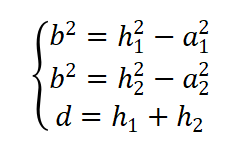
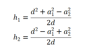
3.2.1计算公式:

由以下关系式

可得

3.2.2二维图源代码:
a1 = 2.5;a2 = 4;d = 7;tao=2.5484e-10;
h1=(d^2+a1^2-a2^2)/(2*d);
h2=(d^2-a1^2+a2^2)/(2*d);
b=sqrt(h1^2-a1^2);
e0 = 10^(-9)/(36*pi);
x = linspace(-10,10,500);
y = linspace(-10,10,500);
theta=linspace(0,2*pi,50);
xr1=h2+a2*cos(theta);
yr1=a2*sin(theta);
xr2=-h1+a1*cos(theta);
yr2=a1*sin(theta);
[xx, yy]=meshgrid(x, y);
fai = tao*log(sqrt((xx-b).^2+yy.^2)./sqrt((xx+b).^2+yy.^2))/(2*pi*e0);
[Ex,Ey] = gradient(fai);
E = sqrt(Ex.^2+Ey.^2);
Ex = Ex./E;Ey = Ey./E;
cv=linspace(min(min(fai)),max(max(fai)),51);
contour(xx,yy,fai,cv,'r-');
title('\fontname{ ËÎÌå }\fontsize{11} 两根半径不同轴线(非嵌套) '),hold on
plot(xr1,yr1,'k','linewidth',2)
plot(xr2,yr2,'k','linewidth',2)
xlabel('x');ylabel('y'),hold off
th=linspace(0,2*pi,51);
x1=-b+0.01*cos(th);
y1=0.01*sin(th);
x2=b+0.01*cos(th);
y2=0.01*sin(th);
for i=[1,5,9,13,17,21,22,23,29,30,31,35,39,43,47]h1=streamline(xx,yy,-Ex,-Ey,x1(i),y1(i)); switch icase 1drawEline(h1,350,351);case {5,47}drawEline(h1,360,361);case {9,43}drawEline(h1,388,389);                case {13,39}drawEline(h1,445,446);case {17,35}drawEline(h1,530,531);case {21,31}drawEline(h1,940,941);    case {22,30}drawEline(h1,1270,1271);case {23,29}drawEline(h1,1930,1931);otherwisecontinueend
endfor i=[24,25,26,27,28]h1=streamline(xx,yy,-Ex,-Ey,x1(i),y1(i));drawEline(h1,1250,1251);
endfor i=[1,2,3,50,49]h1=streamline(xx,yy,Ex,Ey,x2(i),y2(i));drawEline(h1,1250,1249);
end
3.2.3二维图结果:
(实在肝不动了,就不抠细节了)

3.2.4三维图源代码:
a1 = 2.5;a2 = 4;d = 7;tao=2.5484e-10;
h1=(d^2+a1^2-a2^2)/(2*d);
h2=(d^2-a1^2+a2^2)/(2*d);
b=sqrt(h1^2-a1^2);
e0 = 10^(-9)/(36*pi);
x = linspace(-10,10,500);
y = linspace(-10,10,500);
[xx, yy]=meshgrid(x, y);
fai = tao*log(sqrt((xx-b).^2+yy.^2)./sqrt((xx+b).^2+yy.^2))/(2*pi*e0);
fai0 = tao*log(0.05/2.4878)/(2*pi*e0);
F = linspace(-fai0,fai0,60);
[Ex,Ey] = gradient(fai);
E = sqrt(Ex.^2+Ey.^2);
Ex = Ex./E;Ey = Ey./E;
surf(fai);
hold on
shading interp;
h1=streamslice(Ex,Ey);
set(h1,'Color',[0.1 0.9 0.8]);
for j=1:length(h1)ui = interp2(fai,h1(j).XData,h1(j).YData);h1(j).ZData = ui;
end
[c,h]=contour3(fai,F);
h.EdgeColor='k';
h.LineStyle='--';
colormap(jet);
3.2.5三维图结果:

3.3两根半径相同轴线(嵌套,tao已知):
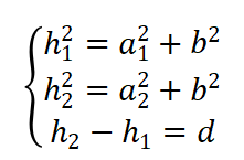
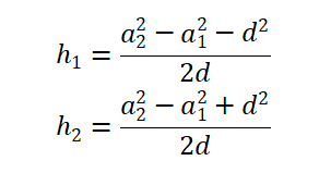
3.3.1计算公式:

由以下关系式

可得

3.3.2二维图源代码
a1 = 1.5;a2 = 4;d = 2;tao=2.5484e-10;
H1=(a2^2-a1^2-d^2)/(2*d);
H2=(a2^2-a1^2+d^2)/(2*d);
b=sqrt(H1^2-a1^2);
e0 = 10^(-9)/(36*pi);
x = linspace(-10,10,500);
y = linspace(-10,10,500);
theta=linspace(0,2*pi,50);
xr1=-H2+a2*cos(theta);
yr1=a2*sin(theta);
xr2=-H1+a1*cos(theta);
yr2=a1*sin(theta);
[xx, yy]=meshgrid(x, y);
fai = tao*log(sqrt((xx-b).^2+yy.^2)./sqrt((xx+b).^2+yy.^2))/(2*pi*e0);
[Ex,Ey] = gradient(fai);
E = sqrt(Ex.^2+Ey.^2);
Ex = Ex./E;Ey = Ey./E;
cv=linspace(min(min(fai)),max(max(fai)),51);
contour(xx,yy,fai,cv,'r-');
title('\fontname{ ËÎÌå }\fontsize{11} 两根半径不同轴线(嵌套)'),hold on
plot(xr1,yr1,'k','linewidth',2)
plot(xr2,yr2,'k','linewidth',2)
xlabel('x');ylabel('y'),hold off
th=linspace(0,2*pi,51);
x1=-b+0.01*cos(th);
y1=0.01*sin(th);
x2=b+0.01*cos(th);
y2=0.01*sin(th);
for i=[1,5,9,13,17,21,22,23,29,30,31,35,39,43,47]h1=streamline(xx,yy,-Ex,-Ey,x1(i),y1(i)); switch icase {1,5,47}drawEline(h1,550,551);case {9,43}drawEline(h1,570,571);                case {13,39}drawEline(h1,680,681);case {17,35}drawEline(h1,950,951);case {21,31}drawEline(h1,1950,1951);    case {22,30}drawEline(h1,2570,2571);case {23,29}drawEline(h1,1230,1231);otherwisecontinueend
endfor i=[24,25,26,27,28]h1=streamline(xx,yy,-Ex,-Ey,x1(i),y1(i));drawEline(h1,1250,1251);
endfor i=[1,2,3,4,48,49,50]h1=streamline(xx,yy,Ex,Ey,x2(i),y2(i));drawEline(h1,1250,1249);
end
3.3.3二维图结果

3.3.4三维图源代码
a1 = 1.5;a2 = 4;d = 2;tao=2.5484e-10;
H1=(a2^2-a1^2-d^2)/(2*d);
H2=(a2^2-a1^2+d^2)/(2*d);
b=sqrt(H1^2-a1^2);
e0 = 10^(-9)/(36*pi);
x = linspace(-10,10,500);
y = linspace(-10,10,500);
[xx, yy]=meshgrid(x, y);
fai = tao*log(sqrt((xx-b).^2+yy.^2)./sqrt((xx+b).^2+yy.^2))/(2*pi*e0);
fai0 = tao*log(0.1/3.7426)/(2*pi*e0);
F = linspace(-fai0,fai0,60);
[Ex,Ey] = gradient(fai);
E = sqrt(Ex.^2+Ey.^2);
Ex = Ex./E;Ey = Ey./E;
surf(fai);
hold on
shading interp;
h1=streamslice(Ex,Ey);
set(h1,'Color',[0.1 0.9 0.8]);
for j=1:length(h1)ui = interp2(fai,h1(j).XData,h1(j).YData);h1(j).ZData = ui;
end
[c,h]=contour3(fai,F);
h.EdgeColor='k';
h.LineStyle='--';
colormap(jet);3.3.5三维图结果

这篇关于基于Matlab的电磁场与波“电轴法”仿真的文章就介绍到这儿,希望我们推荐的文章对编程师们有所帮助!


![C# double[] 和Matlab数组MWArray[]转换](/front/images/it_default2.jpg)


