本文主要是介绍采用PWM调光实现睡眠呼吸灯(STM32),希望对大家解决编程问题提供一定的参考价值,需要的开发者们随着小编来一起学习吧!
引言
在许多的智能手机和家用睡前床灯等场景上,或多或少都可以见到一个呼吸灯的影子。 本文中采用了PWM技术复刻这一呼吸灯效果。
在PWM调光屏幕上,调节亮度并不靠改变功率,而是靠屏幕的亮、灭交替。PWM调光屏幕点亮时并不是持续发光的,而是在不停地点亮、熄灭屏幕。当亮、灭交替够快时,肉眼就会认为手机一直在亮。
在屏幕亮、灭的过程中,灭屏状态持续时间越长,屏幕给肉眼的观感就是亮度越低。点亮的时间越长,灭屏时间就相应减少,屏幕就会变亮。
亮、灭交替的速度越低,对人眼造成不利影响的可能性就越大。但这并不是绝对的,因为每个人对于“闪烁”的敏感程度不同。比如看同一块PWM屏幕,有人没事,有人就会感到疲劳。如果你属于眼睛十分敏感的那部分人,你可能就需要使用高频PWM调光手机,甚至DC调光手机了。
一、PWM概述
1、PWM定义
PWM叫脉冲宽度调制(Pulse Width Modulation),通过编程控制输出方波的频率和占空比(高低电平的比例),广泛应用在测量,通信,功率控制等领域(呼吸灯,电机)。
脉冲:方波、频率(frequency)
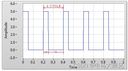
宽度:高电平宽度,占空比(duty)
占空比25%
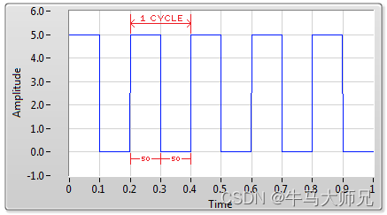
占空比50%
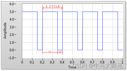
占空比75%
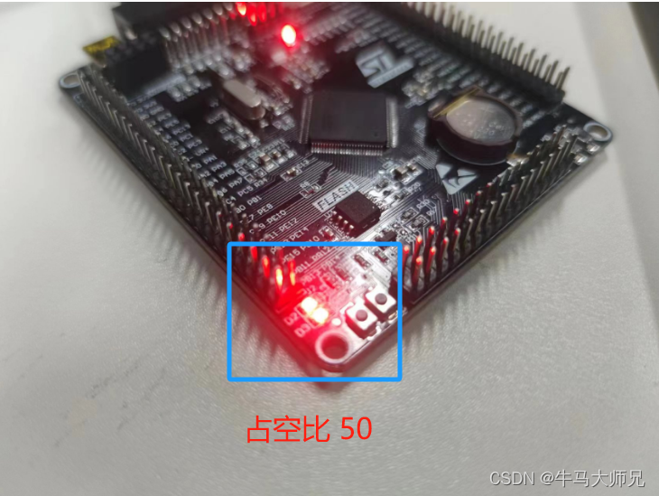
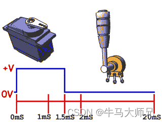
如下所示,通过调节占空比,改变LED亮度以实现本文所描述的呼吸灯效果外,还可以通过调节占空比去控制舵机的转动角度。更深入的运用便是控制机械手、机械臂的运动。
调节亮度
占空比50%
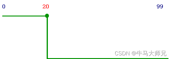
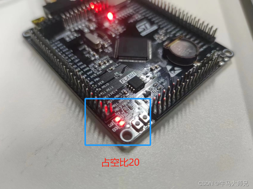
占空比20%
控制舵机运转角度
二、STM32库函数
1、GPIO引脚映射函数----GPIO_PinAFConfig( )
/*** @brief  Changes the mapping of the specified pin.* @param  GPIOx: where x can be (A..K) to select the GPIO peripheral for STM32F405xx/407xx and STM32F415xx/417xx devices*                      x can be (A..I) to select the GPIO peripheral for STM32F42xxx/43xxx devices.*                      x can be (A, B, C, D and H) to select the GPIO peripheral for STM32F401xx devices. * @param  GPIO_PinSource: specifies the pin for the Alternate function.*         This parameter can be GPIO_PinSourcex where x can be (0..15).* @param  GPIO_AFSelection: selects the pin to used as Alternate function.* @retval None*/
void GPIO_PinAFConfig(GPIO_TypeDef* GPIOx, uint16_t GPIO_PinSource, uint8_t GPIO_AF);2、初始化定时器的时间基准----TIM_TimeBaseInit( )
/*** @brief  Initializes the TIMx Time Base Unit peripheral according to *         the specified parameters in the TIM_TimeBaseInitStruct.* @param  TIMx: where x can be  1 to 14 to select the TIM peripheral.* @param  TIM_TimeBaseInitStruct: pointer to a TIM_TimeBaseInitTypeDef structure*         that contains the configuration information for the specified TIM peripheral.* @retval None*/
void TIM_TimeBaseInit(TIM_TypeDef* TIMx, TIM_TimeBaseInitTypeDef* TIM_TimeBaseInitStruct)3、定时器通道1配置----TIM_OC1Init( )
/*** @brief  Initializes the TIMx Channel1 according to the specified parameters in*         the TIM_OCInitStruct.* @param  TIMx: where x can be 1 to 14 except 6 and 7, to select the TIM peripheral.* @param  TIM_OCInitStruct: pointer to a TIM_OCInitTypeDef structure that contains*         the configuration information for the specified TIM peripheral.* @retval None*/
void TIM_OC1Init(TIM_TypeDef* TIMx, TIM_OCInitTypeDef* TIM_OCInitStruct)
注:
通道1:TIM_OC1Init
通道2:TIM_OC2Init
通道3:TIM_OC3Init
通道4:TIM_OC4Init
4、定时器通道1比较值----TIM_SetCompare1( )
/*** @brief  Sets the TIMx Capture Compare1 Register value* @param  TIMx: where x can be 1 to 14 except 6 and 7, to select the TIM peripheral.* @param  Compare1: specifies the Capture Compare1 register new value.* @retval None*/
void TIM_SetCompare1(TIM_TypeDef* TIMx, uint32_t Compare1)
注:
通道1:TIM_SetCompare1
通道2:TIM_SetCompare2
通道3:TIM_SetCompare3
通道4:TIM_SetCompare4
三、函数配置说明
《stm32f4xx中文参考手册》.pdf P433
通用定时器TIM3到TIM5
TIMx_CNT由TIM_TimeBaseStructure.TIM_Period决定;
TIMx_CCR1由TIM_SetComparex(x:1、2、3、4)函数决定;
有效状态由TIM_OCInitStructure.TIM_OCPolarity决定;
频率值:由计数值决定
占空比:由比较值决定
注:要保持一定的占空比时,计数值(TIM_Period)发生变更,比较值(TIM_Pulse)也要发生变更
要设置的比较值 =(TIM_Period+1)* 占空比
TIM_TimeBaseStructure.TIM_Period = 100-1; //输出脉冲的频率100Hz
......
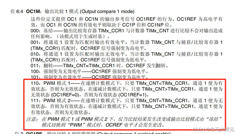
TIM_OCInitStructure.TIM_OCMode = TIM_OCMode_PWM1; //通道工作在PWM模式1
......
TIM_OCInitStructure.TIM_OCPolarity = TIM_OCPolarity_High; //有效状态为高电平
......
TIM_OCInitStructure.TIM_OutputState = TIM_OutputState_Enable;//输出状态使能
......
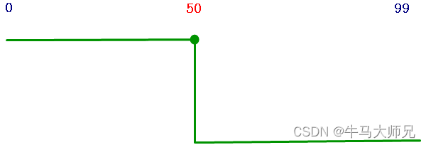
TIM_OCInitStructure.TIM_Pulse = 50; //当前填写值决定了占空比
......调整TIM1通道1的占空比为20%
TIM_SetCompare1(TIM3, 20);四、PWM呼吸灯代码
main.c
#include "stm32f4xx.h"
#include "mypwm.h"int main(void)
{int i = 0;//NVIC_PriorityGroupConfig(NVIC_PriorityGroup_1);LED_TIM3_Init();LED_PWM1_Init();PAout(6) = 1;PCout(5) = 1;while(1){//由暗到亮for(i=0; i<=100; i++){TIM_SetCompare1(TIM3, i);TIM_SetCompare2(TIM3, i);delay_ms(20);}//由亮到暗for(i=100; i>=0; i--){TIM_SetCompare1(TIM3, i);TIM_SetCompare2(TIM3, i);delay_ms(20);}}return 0;
}
mypwm.c
#include "mypwm.h"//LED初始化
void LED_TIM3_Init(void)
{	GPIO_InitTypeDef GPIO_InitStructure;/* TIM3 clock enable */RCC_APB1PeriphClockCmd(RCC_APB1Periph_TIM3, ENABLE);/* GPIOA clock enable */RCC_AHB1PeriphClockCmd(RCC_AHB1Periph_GPIOA, ENABLE);/* GPIOC Configuration: TIM3 CH1 (PA6) */GPIO_InitStructure.GPIO_Pin   = GPIO_Pin_6;GPIO_InitStructure.GPIO_Mode  = GPIO_Mode_AF;GPIO_InitStructure.GPIO_Speed = GPIO_Speed_100MHz;GPIO_InitStructure.GPIO_OType = GPIO_OType_PP;GPIO_InitStructure.GPIO_PuPd  = GPIO_PuPd_NOPULL ;GPIO_Init(GPIOA, &GPIO_InitStructure); /* GPIOC Configuration: TIM3 CH2 (PA7) */GPIO_InitStructure.GPIO_Pin   = GPIO_Pin_7;GPIO_Init(GPIOA, &GPIO_InitStructure); /* Connect TIM3 pins to PA6 PA7 */  GPIO_PinAFConfig(GPIOA, GPIO_PinSource6, GPIO_AF_TIM3);GPIO_PinAFConfig(GPIOA, GPIO_PinSource7, GPIO_AF_TIM3);//熄灭所有灯PAout(6) = 1;PAout(7) = 1;
}//LED的PWM配置
void LED_PWM1_Init(void)
{//NVIC_InitTypeDef NVIC_InitStructure;TIM_TimeBaseInitTypeDef  TIM_TimeBaseStructure;TIM_OCInitTypeDef  TIM_OCInitStructure;RCC_APB1PeriphClockCmd(RCC_APB1Periph_TIM3, ENABLE);/* Time base configuration */TIM_TimeBaseStructure.TIM_Period = 100-1; //100Hz  定时时间的配置,也就是配置重载值,而重载值会传递给计数值TIM_TimeBaseStructure.TIM_Prescaler = 8400 - 1;	  //配置分频值,确定定时器的时钟频率TIM_TimeBaseStructure.TIM_CounterMode = TIM_CounterMode_Up; //向上计数,0->TIM_Period就会触发中断请求TIM_TimeBaseInit(TIM3, &TIM_TimeBaseStructure);/* PWM1 Mode configuration: Channel1 */TIM_OCInitStructure.TIM_OCMode = TIM_OCMode_PWM1;TIM_OCInitStructure.TIM_OutputState = TIM_OutputState_Enable;TIM_OCInitStructure.TIM_Pulse = 50;	TIM_OCInitStructure.TIM_OCPolarity = TIM_OCPolarity_High;TIM_OC1Init(TIM3, &TIM_OCInitStructure);TIM_OC1PreloadConfig(TIM3, TIM_OCPreload_Enable);/* PWM1 Mode configuration: Channel2 */TIM_OCInitStructure.TIM_Pulse = 50;TIM_OC2Init(TIM3, &TIM_OCInitStructure);/* TIM3 enable counter */TIM_Cmd(TIM3, ENABLE);//	NVIC_InitStructure.NVIC_IRQChannel = TIM3_IRQn;
//	NVIC_InitStructure.NVIC_IRQChannelPreemptionPriority = 0;
//	NVIC_InitStructure.NVIC_IRQChannelSubPriority = 1;
//	NVIC_InitStructure.NVIC_IRQChannelCmd = ENABLE;
//	NVIC_Init(&NVIC_InitStructure);
}
mypwm.h
#ifndef __MY_PWM_H
#define __MY_PWM_H#include "stm32f4xx.h"//位带操作#define PAout(n) (*(uint32_t *)(0x42000000 +(GPIOA_BASE+0x14-0x40000000)*32 + n*4))#define PBout(n) (*(uint32_t *)(0x42000000 +(GPIOB_BASE+0x14-0x40000000)*32 + n*4))#define PCout(n) (*(uint32_t *)(0x42000000 +(GPIOC_BASE+0x14-0x40000000)*32 + n*4))#define PBin(n) (*(uint32_t *)(0x42000000 +(GPIOB_BASE+0x10-0x40000000)*32 + n*4))#define PCin(n) (*(uint32_t *)(0x42000000 +(GPIOC_BASE+0x10-0x40000000)*32 + n*4))void LED_Init(void);void LED_TIM3_Init(void);void LED_PWM1_Init(void);#endif注意:并不是每个GPIO引脚都可以进行TIM定时器配置,需要看ST官方的芯片手册,是否有对应的引脚复用功能。如下图所示的为STM32F407VET6芯片的部分截图。
普通IO也可以输出PWM,很少直接用MCU的IO口直接输出,因为那样需要消耗大量的MCU资源。

这篇关于采用PWM调光实现睡眠呼吸灯(STM32)的文章就介绍到这儿,希望我们推荐的文章对编程师们有所帮助!


