本文主要是介绍华大HC32F460跑马灯实验,希望对大家解决编程问题提供一定的参考价值,需要的开发者们随着小编来一起学习吧!
1.GPIO编程基础
1.1 GPIO编程定义说明
GPIO(General Purpose Input Output)官方说法叫“通用输入输出”,一般一组端口的写法为Px,在HC32F46微控制器100脚芯片中,x=A~E,H,如PA表示PortA端口组。在编程中被定义如下。
typedef enum en_port
{PortA = 0,      ///< port group APortB = 1,      ///< port group BPortC = 2,      ///< port group CPortD = 3,      ///< port group DPortE = 4,      ///< port group EPortH = 5,      ///< port group H
}en_port_t;
每组端口一般为16个I/O引脚(有些端口不足16个,例如HC32F460微控制器100脚芯片H组端口只有3个I/O引脚),每个引脚用Pxy表示,其中x= A~E,H, y=0~15;引脚在编程中定义如下。
typedef enum en_pin
{Pin00 = (1 <<  0), 	///< Pin index 00 of each port groupPin01 = (1 <<  1),		///< Pin index 01 of each port groupPin02 = (1 <<  2),		///< Pin index 02 of each port groupPin03 = (1 <<  3),		///< Pin index 03 of each port groupPin04 = (1 <<  4),		///< Pin index 04 of each port groupPin05 = (1 <<  5),		///< Pin index 05 of each port groupPin06 = (1 <<  6),		///< Pin index 06 of each port groupPin07 = (1 <<  7), 	///< Pin index 07 of each port groupPin08 = (1 <<  8),		///< Pin index 08 of each port groupPin09 = (1 << 9,		///< Pin index 09 of each port groupPin10 = (1 << 10,		///< Pin index 10 of each port groupPin11 = (1 << 11,		///< Pin index 11 of each port groupPin12 = (1 << 12,		///< Pin index 12 of each port groupPin13 = (1 << 13,		///< Pin index 13 of each port groupPin14 = (1 << 14,		///< Pin index 14 of each port groupPin15 = (1 << 15,		///< Pin index 15 of each port groupPinAll= 0Xffff,			///< All pins selected
}en_pin_t;
GPIO除作为普通输入输出之外,还有很多复用功能,例如作为usart串口的数据收发信号线,外部中断功能等。在编程中对每个复用功能进行了功能号的定义,可以在I/O口初始化的时候使用(默认为GPIO)。
typedef enum en_port_func
{Func_Gpio       = 0u, 	 ///< function set to gpioFunc_Fcmref     = 1u, 	 ///< function set to fcm referenceFunc_Rtcout     = 1u,  	 ///< function set to rtc outputFunc_Vcout      = 1u, 	 ///< function set to vc outputFunc_Adtrg      = 1u,	 ///< function set to adc triggerFunc_Mclkout    = 1u, 	 ///< function set to mclk outputFunc_Tim4       = 2u,	 ///< function set to timer4Func_Tim6       = 3u, 	 ///< function set to timer6Func_Tima0      = 4u, 	 ///< function set to timerAFunc_Tima1      = 5u,      ///< function set to timerAFunc_Tima2      = 6u,      ///< function set to timerAFunc_Emb        = 6u,     ///< function set to embFunc_Usart_Ck   = 7u,      ///< function set to usart clkFunc_Spi_Nss    = 7u,      ///< function set to spi nssFunc_Qspi       = 7u,     ///< function set to qspiFunc_Key        = 8u,     ///< function set to keyFunc_Sdio       = 9u,     ///< function set to sdioFunc_I2s        = 10u,    ///< function set to i2sFunc_UsbF       = 10u,    ///< function set to usb full speedFunc_Evnpt      = 14u,    ///< function set to event portFunc_Eventout   = 15u,    ///< function set to event outFunc_Usart1_Tx  = 32u,    ///< function set to usart tx of ch.1Func_Usart3_Tx  = 32u,    ///< function set to usart tx of ch.3Func_Usart1_Rx  = 33u,    ///< function set to usart rx of ch.1Func_Usart3_Rx  = 33u,    ///< function set to usart rx of ch.3Func_Usart1_Rts = 34u, 	 ///< function set to usart rts of ch.1Func_Usart3_Rts = 34u,    ///< function set to usart rts of ch.3Func_Usart1_Cts = 35u,    ///< function set to usart cts of ch.1Func_Usart3_Cts = 35u,    ///< function set to usart cts of ch.3Func_Usart2_Tx  = 36u,    ///< function set to usart tx of ch.2Func_Usart4_Tx  = 36u,    ///< function set to usart tx of ch.4Func_Usart2_Rx  = 37u,    ///< function set to usart rx of ch.2Func_Usart4_Rx  = 37u,    ///< function set to usart rx of ch.4Func_Usart2_Rts = 38u,    ///< function set to usart rts of ch.2Func_Usart4_Rts = 38u,    ///< function set to usart rts of ch.4Func_Usart2_Cts = 39u,    ///< function set to usart cts of ch.2Func_Usart4_Cts = 39u,    ///< function set to usart cts of ch.4Func_Spi1_Mosi  = 40u,    ///< function set to spi mosi of ch.1Func_Spi3_Mosi  = 40u,    ///< function set to spi mosi of ch.3Func_Spi1_Miso  = 41u,    ///< function set to spi miso of ch.1Func_Spi3_Miso  = 41u,    ///< function set to spi miso of ch.3Func_Spi1_Nss0  = 42u,    ///< function set to spi nss0 of ch.1Func_Spi3_Nss0  = 42u,    ///< function set to spi nss0 of ch.3Func_Spi1_Sck   = 43u,    ///< function set to spi sck of ch.1Func_Spi3_Sck   = 43u,    ///< function set to spi sck of ch.3Func_Spi2_Mosi  = 44u,    ///< function set to spi mosi of ch.2Func_Spi4_Mosi  = 44u,    ///< function set to spi mosi of ch.2Func_Spi2_Miso  = 45u,    ///< function set to spi miso of ch.4Func_Spi4_Miso  = 45u,    ///< function set to spi miso of ch.4Func_Spi2_Nss0  = 46u,    ///< function set to spi nss0 of ch.2Func_Spi4_Nss0  = 46u,    ///< function set to spi nss0 of ch.4Func_Spi2_Sck   = 47u,    ///< function set to spi sck of ch.2Func_Spi4_Sck   = 47u,    ///< function set to spi sck of ch.4Func_I2c1_Sda   = 48u,    ///< function set to i2c sda of ch.1Func_I2c3_Sda   = 48u,    ///< function set to i2c sda of ch.3Func_I2c1_Scl   = 49u,    ///< function set to i2c scl of ch.1Func_I2c3_Scl   = 49u,    ///< function set to i2c scl of ch.3Func_I2c2_Sda   = 50u,    ///< function set to i2c sda of ch.2Func_Can1_Tx    = 50u,    ///< function set to can tx of ch.1Func_I2c2_Scl   = 51u,     ///< function set to i2c scl of ch.2Func_Can1_Rx    = 51u,    ///< function set to can rx of ch.1Func_I2s1_Sd    = 52u,    ///< function set to i2s sd of ch.1Func_I2s3_Sd    = 52u,    ///< function set to i2s sd of ch.3Func_I2s1_Sdin  = 53u,    ///< function set to i2s sdin of ch.1Func_I2s3_Sdin  = 53u,    ///< function set to i2s sdin of ch.3Func_I2s1_Ws    = 54u,    ///< function set to i2s ws of ch.1Func_I2s3_Ws    = 54u,    ///< function set to i2s ws of ch.3Func_I2s1_Ck    = 55u,    ///< function set to i2s ck of ch.1Func_I2s3_Ck    = 55u,    ///< function set to i2s ck of ch.3Func_I2s2_Sd    = 56u,    ///< function set to i2s sd of ch.2Func_I2s4_Sd    = 56u,    ///< function set to i2s sd of ch.4Func_I2s2_Sdin  = 57u,    ///< function set to i2s sdin of ch.2Func_I2s4_Sdin  = 57u,    ///< function set to i2s sdin of ch.4Func_I2s2_Ws    = 58u,    ///< function set to i2s ws of ch.2Func_I2s4_Ws    = 58u,    ///< function set to i2s ws of ch.4Func_I2s2_Ck    = 59u,    ///< function set to i2s ck of ch.2Func_I2s4_Ck    = 59u,    ///< function set to i2s ck of ch.4
}en_port_func_t;
I/O引脚的应用模式一般有三种:输入模式、输出模式、模拟模式,在代码中被定义如下。
typedef enum en_pin_mode
{Pin_Mode_In  = 0,         ///< GPIO 输入模式Pin_Mode_Out = 1,         ///< GPIO 输出模式Pin_Mode_Ana = 2,         ///< GPIO 模拟模式
}en_pin_mode_t;
其中输出模式又有两种:开漏输出和CMOS模式。定义如下:
typedef enum en_pin_o_type
{Pin_OType_Cmos = 0,                 ///< CMOSPin_OType_Od   = 1,                 ///< Open Drain
}en_pin_o_type_t;
为了更好的对GPIO进行初始化,专门定义一个初始化结构,每次子需要对该结构定义的变量中进行初始化赋值后,在初始化函数中调用该变量即可。
typedef struct stc_port_init
{en_pin_mode_t  enPinMode; ///< Set pin mode @ref en_pin_mode_ten_functional_state_t   enLatch;  ///< Pin output latch enableen_functional_state_t   enExInt;  ///< al int enableen_functional_state_t   enInvert;  ///< Pin input/output invert enableen_functional_state_t   enPullUp; ///< Internal pull-up resistor enableen_pin_drv_t   enPinDrv; ///< Drive capacity setting @ref en_pin_drv_ten_pin_o_type_t  enPinOType; ///< Output mode setting @ref \en_pin_o_type_ten_functional_state_t  enPinSubFunc;   ///< Pin sub-function enable
}stc_port_init_t;
1.2 GPIO库函数介绍
GPIO通用法的库函数不多,函数列表如下:
en_result_t PORT_Init(en_port_t enPort, uint16_t u16Pin, \const stc_port_init_t *pstcPortInit);en_result_t PORT_DeInit(void);void PORT_Unlock(void);void PORT_Lock(void);en_result_t PORT_DebugPortSetting(uint8_t u8DebugPort, \en_functional_state_t enFunc);en_result_t PORT_PubSetting(const stc_port_pub_set_t *pstcPortPubSet);uint16_t PORT_GetData(en_port_t enPort);en_flag_status_t PORT_GetBit(en_port_t enPort, en_pin_t enPin);en_result_t PORT_SetPortData(en_port_t enPort, uint16_t u16Pin);en_result_t PORT_ResetPortData(en_port_t enPort, uint16_t u16Pin);en_result_t PORT_OE(en_port_t enPort, uint16_t u16Pin, \en_functional_state_t enNewState);en_result_t PORT_SetBits(en_port_t enPort, uint16_t u16Pin);en_result_t PORT_ResetBits(en_port_t enPort, uint16_t u16Pin);en_result_t PORT_Toggle(en_port_t enPort, uint16_t u16Pin);en_result_t PORT_AlwaysOn(en_port_t enPort, en_functional_state_t enNewState);en_result_t PORT_SetFunc(en_port_t enPort, uint16_t u16Pin, \ en_port_func_t enFuncSel, en_functional_state_t enSubFunc);en_result_t PORT_SetSubFunc(en_port_func_t enFuncSel);
此处重点讲初始化、I/0引脚置低、I/0引脚置高、I/0引脚取反、I/0引脚状态获取几个函数的原型及用法。
【GPIO初始化函数】
函数原型:en_result_t PORT_Init(en_port_t enPort, uint16_t u16Pin, const stc_port_init_t *pstcPortInit)
输 入:
enPort:GPIO端口号, 参照ref en_port_t结构定义;
u16Pin:GPIO 引脚号, 参照ref en_pin_t结构定义;
pstcPortInit:初始化结构变量,参照stc_port_init_t结构定义变量。
输 出:初始化结果状态,一般不用;
功 能:初始化指定GPIO端口号的指定引脚;
举 例:PORT_Init( PortA, Pin05, &stcPortInit )。
【I/0引脚置低函数】
函数原型:en_result_t PORT_ResetBits(en_port_t enPort, uint16_t u16Pin)
输 入:
enPort:GPIO端口号, 参照ref en_port_t结构定义;
u16Pin:GPIO 引脚号, 参照ref en_pin_t结构定义;
输 出:操作结果状态,一般不用;
功 能:GPIO端口号的指定引脚输出低电平(0);
举 例:PORT_ResetBits ( PortA, Pin05 )。
【I/0引脚置高函数】
函数原型:en_result_t PORT_SetBits(en_port_t enPort, uint16_t u16Pin)
输 入:
enPort:GPIO端口号, 参照ref en_port_t结构定义;
u16Pin:GPIO 引脚号, 参照ref en_pin_t结构定义;
输 出:操作结果状态,一般不用;
功 能:GPIO端口号的指定引脚输出高电平(1);
举 例:PORT_ SetBits ( PortA, Pin05 )。
2 实验1:跑马灯实验
2.1 实验目标
本实验主要通过对GPIO驱动操作,控制LED的亮或灭,从而实现LED跑马灯动态效果显示。
2.2 实验准备
硬件搭建:ZW-HC32F460-BZ标准版开发板1套
软件搭建:MDK5.22
2.3 硬件原理
板载4个LED功能指示灯,LED1、LED2、LED3、LED4分别对应PA5、PA6、PA7、PA8引脚。原理图如下所示。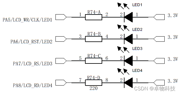
从图中可以看出引脚输出低电平,对应LED灯被点亮;反之熄灭。
2.4 驱动代码
为了简化编程,让用户快速上手,我公司针对LED驱动文件进行了深度优化编写,提供开源的led.c和led.h以供用户使用,现将源文件关键定义及函数做说明。
【LED定义】
1)LED编号定义
本案使用四个LED灯,对四个LED序号进行如下定义。
#define LED1				0x0001
#define LED2				0x0002
#define LED3				0x0004
#define LED4				0x0008
2)LED端口和引脚定义
因为LED灯是直接GPIO引脚驱动的,实际上控制LED灯亮灭就是直接控制GPIO引脚置高置低操作,其使用方法与GPIO操作类似。这里定义了各个LED的端口号以及引脚号。
#define BSP_LED1_PORT	( PortA + LED1_PORT_NUM )
#define BSP_LED1_PIN		( Pin00 << LED1_PIN_NUM )
#define BSP_LED2_PORT 	( PortA + LED2_PORT_NUM )
#define BSP_LED2_PIN		( Pin00 << LED2_PIN_NUM )
#define BSP_LED3_PORT	( PortA + LED3_PORT_NUM )
#define BSP_LED3_PIN		( Pin00 << LED3_PIN_NUM )
#define BSP_LED4_PORT	( PortA + LED4_PORT_NUM )
#define BSP_LED4_PIN		( Pin00 << LED4_PIN_NUM )
备注:为了文件的扩展性,本文件采用灵活配置LED端口及引脚的方式,也就是用户可以自定义每个LED灯对应的端口号及引脚。以上显示的LEDx_PORT_NUM和LEDx_PIN_NUM均随着配置不同动态变化的。当然你也可以直接定义指定端口和引脚(以LED1为例)。
#define BSP_LED1_PORT	 PortA )
#define BSP_LED1_PIN		 Pin05
说明:以上定义均在led.h文件中,为了更好的通用及扩展性,在文件中定义了10个LED,也就是本源文件不做任何修改的前提下可以支持10个LED灯外设的控制操作,用户只需要通过实际的原理图勾选配置对应的LED使能及对应引脚即可。
【LED初始化】
初始化函数与初始化GPIO方法一样。
函数原型: void LedInt( void )
功能说明: LED灯初始化
输入参数: 无
输出参数: 无
特殊备注: 这里根据定义的LED数据全部初始化,需要配合的参数
1.BSP_LED_NUM (宏)
2.BSP_LED_PORT_PIN (结构体)
void LedInt( void )
{u8 i;stc_port_init_t stcPortInit;MEM_ZERO_STRUCT( stcPortInit );            //结构体初始化stcPortInit.enPinMode = Pin_Mode_Out;      //设置输出模式for (i = 0U; i < BSP_LED_NUM; i++){PORT_Init( BSP_LED_PORT_PIN[i].port, BSP_LED_PORT_PIN[i].pin, &stcPortInit );}
}
【点亮LED】
点亮LED调用PORT_ ResetBits ()函数,将对应的GPIO引脚置低即可。
函数原型: void LedOn( u8 u8Led )
功能说明: 点亮指定的LED
输入参数: 指定LED序号
输出参数: 无
特殊备注: 无
void LedOn( u8 u8Led )
{u8 i; for (i = 0U; i < BSP_LED_NUM; i++){if (0U != ((u8Led >> i) & 1U)){PORT_ResetBits(BSP_LED_PORT_PIN[i].port, \BSP_LED_PORT_PIN[i].pin);}}
}
【熄灭LED】
熄灭LED调用PORT_SetBits()函数,将对应的GPIO引脚置高即可。
函数原型: void LedOff( u8 led )
功能说明: 关闭指定LED
输入参数: 指定LED序号
输出参数: 无
特殊备注: 无
void LedOff( u8 led )
{u8 i;  for (i = 0U; i < BSP_LED_NUM; i++){if ( 0U != ( ( led >> i ) & 1U ) ){PORT_SetBits( BSP_LED_PORT_PIN[i].port, \SP_LED_PORT_PIN[i].pin );}}
}
【LED状态取反】
LED状态改变调用PORT_ GetBit ()函数,将对应的GPIO引脚状态取反。
函数原型: void LedToggle( u8 led )
功能说明: 取反R指定LED灯状态
输入参数: 指定LED序号
输出参数: 无
特殊备注: 无
void LedToggle( u8 led )
{u8 i;  for (i = 0U; i < BSP_LED_NUM; i++){if ( 0U != ( ( led >> i ) & 1U ) ){PORT_Toggle( BSP_LED_PORT_PIN[i].port, BSP_LED_PORT_PIN[i].pin );}}
}
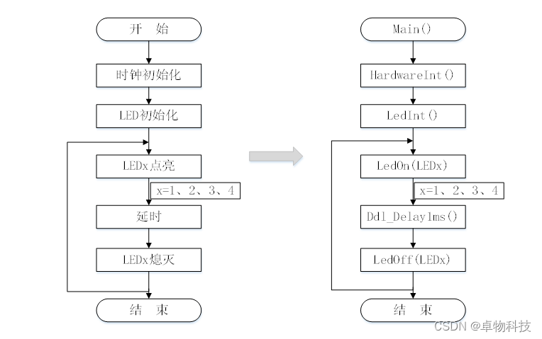
2.5 主流程图
2.6 实验过程
【第一步:新建/配置工程】
参见以下四点,将工程模板复制到实验目录下,将工程名改为LED。
【1:工程名称修改】
工程模板工程文件统一命名为:MDK-HC32F460。用户可以根据自己应用对工程重新命名,只需要修改MDK-HC32F460.uvprojx文件和MDK-HC32F460.uvoptx文件即可。比如我的修改为Template-HC32F460。


【2:FWLibCfg.h配置】
打开工程模板,对FWLibCfg.h进行初始化配置。
1)调试串口配置

建议配置USB转串口,这样即可为板子供电,还可以使用串口调试信息。
2)外设资源配置
如果使用了调试串口配置,CLK_EN、EFM_EN、GPIO_EN、PWC_EN、SRAM_EN、UTILITY_EN必须勾选,缺一不可。
配置完后可以编译看是否正确。
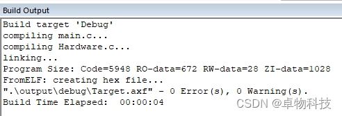
此时模板的基本配置就完成,可以在基础上增加用户功能代码。这里我们使用库函数简要的点亮一个LED灯测试下。
【3:增加用户代码】
1)定义Port初始化结构体
stc_port_init_t stcPortInit; //定义Port初始化结构体2)初始化LED1对应的PA5引脚
MEM_ZERO_STRUCT(stcPortInit);
stcPortInit.enPinMode = Pin_Mode_Out;
stcPortInit.enExInt = Enable;
stcPortInit.enPullUp = Enable;
PORT_Init(PortA, Pin05, &stcPortInit);
初始化输出模式。
3)点亮LED1
只需要讲PA5置为低电平即可。
PORT_ResetBits(PortA, Pin05);//PA5输出低电平【4:验证结果】
编译下载即可。LED1被点亮,同时串口输出“The Template!”内容,如下图所示。

勾选FWLibCfg.h配置中的CLK_EN、EFM_EN、GPIO_EN、PWC_EN、SRAM_EN、UTILITY_EN选项
【第二步:添加LED模块驱动】
将led.c和led.h复制到\实验1跑马灯实验\Hardware\OnBoard路径下,同时将led.c添加到工程中Hardware/OnBoard下。

【第三步:初始化编程】
1)添加led头文件
在main.c文件中先添加 led.h头文件。
#include "led.h"2)配置led控制引脚
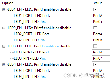
打开led.h(一般将h文件添加到c文件并编译,即可在c文件下方显示出该h文件)文件,在下方选择 “Configuration Wizard”标签,即可出现配置界面。将LED1~LED4进行如下配置(与原理图引脚对应)。
3)LED初始化
在主函数中调用LED初始化函数LedInt()。
LedInt();【第四步:跑马灯实现】
四个LED实现跑马灯控制逻辑很简单,LED灯依次点亮熄灭即可。
while(1){LedOn(LED1);Ddl_Delay1ms(200);LedOff(LED1); LedOn(LED2); Ddl_Delay1ms(200);LedOff(LED2);LedOn(LED3);Ddl_Delay1ms(200);LedOff(LED3);LedOn(LED4);Ddl_Delay1ms(200);LedOff(LED4);}
【第五步:下载验证】
连接好硬件。
编译下载运行该程序,即可看到板载的四个LED灯循环依次点亮熄灭。
可以调整延时时间,观察显示效果。
2.7 实验扩展
1)先将四个LED依次点亮,再依次熄灭;如此循环。
2)从LED1到LED4依次点亮,再从LED4到LED1依次熄灭;如此循环。
如果您有相关问题需要咨询或有宝贵意见想要提出,欢迎在评论区留言或者私信联系,我们将竭诚与您沟通。
编者寄语:时光积攒经验,实践塑造成长。
成都卓物科技有限公司
2022年11月24日
这篇关于华大HC32F460跑马灯实验的文章就介绍到这儿,希望我们推荐的文章对编程师们有所帮助!


