本文主要是介绍[C#]WPF绘制一个正方体并调整视场角,希望对大家解决编程问题提供一定的参考价值,需要的开发者们随着小编来一起学习吧!
大部分源码参考Github,是一本名为WPF-3D的书的代码,有条件的可以买下实体书。
本文源码:Cube.zip
文章目录
- xml写法
- 调整相机视场角
- cs写法
xml写法
若只是希望新建一个下面这样简单的3D图形,那么只需修改xml就能实现。
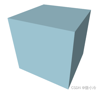
其主要分为两个部分,如下面的代码所示,其中ModelVisual3D即位集合模型,而<Viewport3D.Camera则代表相机视角。我们在屏幕上所看到的三维图,实际上是相机拍摄到并转化为二维的图。
<Window><Viewport3D><Viewport3D.Camera></Viewport3D.Camera><ModelVisual3D><ModelVisual3D.Content><Model3DGroup></Model3DGroup></ModelVisual3D.Content></ModelVisual3D></Viewport3D>
</Window>
其中,相机部分主要有四个参数,分别是位置Position,视角LookDirection,视场角FieldOfView。
第四个参数upDirection用于规定正向,相当于照片拍出来之后要以哪边为正。
<Viewport3D.Camera><PerspectiveCamera Position = "1.5, 2, 3"LookDirection = "-1.5, -2, -3"FieldOfView = "60"UpDirection = "0, 1, 0"/>
</Viewport3D.Camera>
接下来,Model3DGroup则表示即将绘制的几何体,其中最重要的当然是GeometryModel3D,用于规定生成几何体的点。
在WPF中,三维图形必须通过面的形式展现出来,而每生成一个面,则需要三个点。也就是说,通过一个又一个的三角形来拼接成几何体的表面。
所以,尽管希望生成一个正方体,但并不可以让正方体边上的四边形作为最小的面元。
在设置好三维图形的几何要素之后,则可设置其表面颜色和光线颜色。其中DiffuseMaterial中的Brush属性记为几何体表面颜色。
AmbientLight和DirectionLight分别代表背景光和前景光。
<Model3DGroup><!-- Lights --><AmbientLight Color="Gray" /><DirectionalLight Color="Gray" Direction="1,-2,-3" /><GeometryModel3D><GeometryModel3D.Geometry><!-- Cube --><MeshGeometry3DPositions="-1,-1,-1   1,-1,-1   1,-1, 1  -1,-1, 1-1,-1, 1   1,-1, 1   1, 1, 1  -1, 1, 11,-1, 1   1,-1,-1   1, 1,-1   1, 1, 11, 1, 1   1, 1,-1  -1, 1,-1  -1, 1, 1-1,-1, 1  -1, 1, 1  -1, 1,-1  -1,-1,-1 -1,-1,-1  -1, 1,-1   1, 1,-1   1,-1,-1"TriangleIndices="0  1  2     2  3  04  5  6     6  7  48  9 10    10 11  812 13 14    14 15 1216 17 18    18 19 1620 21 22    22 23 20" /></GeometryModel3D.Geometry><GeometryModel3D.Material><DiffuseMaterial Brush="LightBlue" /></GeometryModel3D.Material></GeometryModel3D>
</Model3DGroup>
调整相机视场角
和位置、方向这两个参数相比,视场角并不是那么容易理解,毕竟人眼的视场角几乎是恒定的,所以体会不到视场角发生变化所带来的视野的不同。
所以接下来新建一个slider来绑定视场角,从而直观地感受一下视场角所带来的差别

其代码为
<DockPanel LastChildFill="True"><WrapPanel DockPanel.Dock="Top"><Slider Width="200" Value="60" Maximum="170" Minimum="1" x:Name="sAngle"/><TextBox Text="{Binding ElementName=sAngle,Path=Value, UpdateSourceTrigger=PropertyChanged, Mode=TwoWay}" Margin="0 5" Width="30"/></WrapPanel><Viewport3D></Viewport3D>
</DockPanel>
此外,需要将PerspectiveCamera中的FieldOfView改为FieldOfView = "{Binding Value, ElementName=sAngle}"。
cs写法
将代码全部写在xml端虽然很便携很直观,但在涉及到某些交互操作时,未必十分灵活。好在任何xml端的代码都可以写在cs端
// 窗口加载时执行
private void Window_Loaded(object sender, RoutedEventArgs e)
{// 定义WPF组件ModelVisual3D visual3d = new ModelVisual3D();Model3DGroup group3d = new Model3DGroup();//对应xaml中ModelVisual3D.Contentvisual3d.Content = group3d; //visual3d是mainViewport的子控件mainViewport.Children.Add(visual3d);//定义相机、光线和模型.DefineCamera(mainViewport);DefineLights(group3d);DefineModel(group3d);
}// 定义相机
private void DefineCamera(Viewport3D viewport)
{Point3D p = new Point3D(1.5, 2, 3);Vector3D lookDirection = new Vector3D(-p.X, -p.Y, -p.Z);Vector3D upDirection = new Vector3D(0, 1, 0);double fieldOfView = 60;//对应PerspectiveCamera的四个参数PerspectiveCamera camera = new PerspectiveCamera(p, lookDirection, upDirection, fieldOfView);viewport.Camera = camera;
}// 定义光线.
private void DefineLights(Model3DGroup group)
{group.Children.Add(new AmbientLight(Colors.Gray));Vector3D direction = new Vector3D(1, -2, -3);group.Children.Add(new DirectionalLight(Colors.Gray, direction));
}
接下来是比较复杂的定义模型,其实并不复杂,只是点有点多,如果像写xaml那样写,强迫症可能受不了。
考虑到正方体共有8个顶点,6个面,每个面需要两个三角形,则一共需要12个三角形,总计36组顶点号。
对于每个正方形而言,若生成两个三角形,由于有一条重合的边,故而四个点累计使用6次。若想让点号递增时显得自然一些,则可以让每个面生成四个点,即总计24个点。如此一来,拼接点号为0,1,2,3的正方形,只需用到0,1,2和2,3,0两组点即可。
而正方体的六个面的点的坐标也很有特点,即必有一个坐标轴的分量是不变的,而另外两个坐标轴分量则遍历所有可能的取值。这个逻辑相对来说有些复杂,所以就不改了。
最终得到cs代码如下。
// 定义模型
private void DefineModel(Model3DGroup group)
{// Create the geometry.MeshGeometry3D mesh = new MeshGeometry3D();// Define the positions.Point3D[] points ={new Point3D(-1, -1, -1), new Point3D(1, -1, -1),new Point3D(1, -1, 1), new Point3D(-1, -1, 1),new Point3D(-1, -1, 1), new Point3D(1, -1, 1),new Point3D(1, 1, 1), new Point3D(-1, 1, 1),new Point3D(1, -1, 1), new Point3D(1, -1, -1),new Point3D(1, 1, -1), new Point3D(1, 1, 1),new Point3D(1, 1, 1), new Point3D(1, 1, -1),new Point3D(-1, 1, -1), new Point3D(-1, 1, 1),new Point3D(-1, -1, 1), new Point3D(-1, 1, 1),new Point3D(-1, 1, -1), new Point3D(-1, -1, -1),new Point3D(-1, -1, -1), new Point3D(-1, 1, -1),new Point3D(1, 1, -1), new Point3D(1, -1, -1),};foreach (Point3D point in points) mesh.Positions.Add(point);// Define the triangles.Tuple<int, int, int>[] triangles = new Tuple<int, int, int>[12];for (int i = 0; i < triangles.Length; i++){int tmp = i%2==0 ? 2 : -2;triangles[i] = new Tuple<int, int, int>(2 * i, 2 * i + 1, 2 * i + tmp);}foreach (var tup in triangles){mesh.TriangleIndices.Add(tup.Item1);mesh.TriangleIndices.Add(tup.Item2);mesh.TriangleIndices.Add(tup.Item3);}DiffuseMaterial material = new DiffuseMaterial(Brushes.LightBlue);GeometryModel3D model = new GeometryModel3D(mesh, material);group.Children.Add(model);
}
这篇关于[C#]WPF绘制一个正方体并调整视场角的文章就介绍到这儿,希望我们推荐的文章对编程师们有所帮助!


