本文主要是介绍ZYNQ的定时器们(三)TTC定时器到底能干啥?,希望对大家解决编程问题提供一定的参考价值,需要的开发者们随着小编来一起学习吧!
**
ZYNQ的定时器们(三)TTC定时器到底能干啥?
**
本文转载自:https://zhuanlan.zhihu.com/p/31643799?from_voters_page=true
ZYNQPS部分的最后一种定时器TTC在UG585中的描述只有6页(P244-249),SDK中的API函数有15个,宏定义太多了,就没数了。那么TTC能干啥?忙完这阵子后终于可以来跟各位说道说道了。

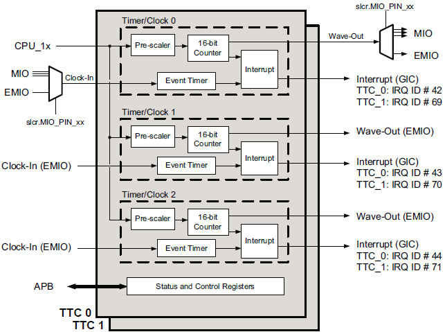
TTC定时器直译过来就是三路定时器,而ZYNQ中的PS有两个TTC,每一个定时器有三路,一共是6路。
从上面的框图可以看出TTC每一路的功能可以分为三种:
- 传统定时计数器(Overflow mode、Interval mode),这个和其他定时器一样通过在每个计数时钟周期向上或向下计数来获得固定的时间间隔;
- PWM输出(Overflow mode、Interval mode),可以输出固定频率和占空比的方波;
- 脉宽计数器(Event Timer),针对外部输入脉冲记录其脉冲宽度;
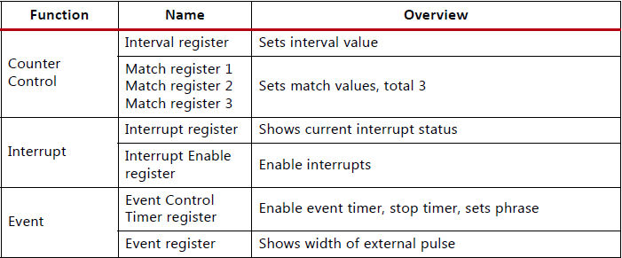
那么操控这些模式肯定需要读写相关寄存器,下面就是每一路TTC定时器的相关寄存器:


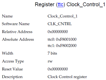
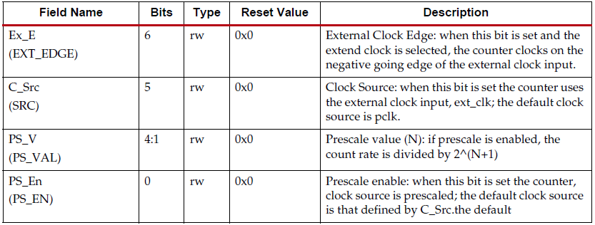
时钟控制寄存器(Clock Control register):


计数器控制寄存器(Counter Control register):
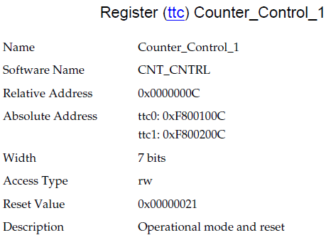
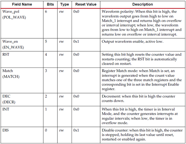

计数器数值寄存器(Counter Value register):


间隔寄存器(Interval register):

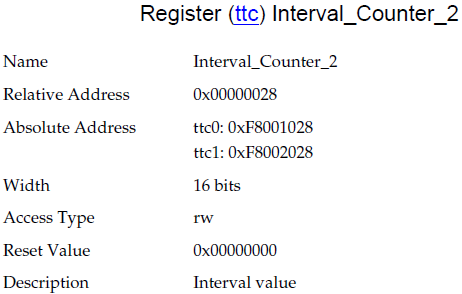


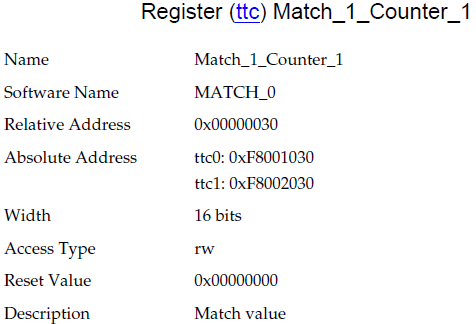
匹配值寄存器(Match register1、2、3):


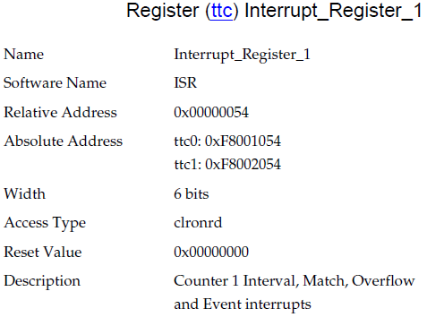
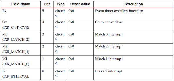
中断寄存器(Interrupt register):

中断允许寄存器(Interrupt Enable register):

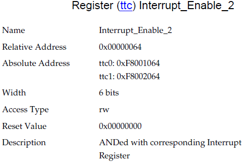


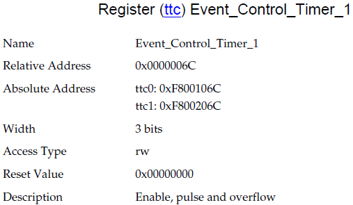
脉宽计数器控制寄存器(Event Control Timer register):
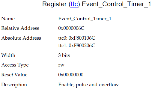


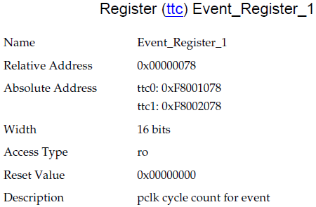
脉宽寄存器(Event register):
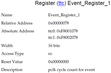

在你看懂之后完全可以不用SDK中的函数,直接用寄存器操作就能得到你想要的效果,不过需要注意的是TTC定时器是16位定时器,虽然可以用分频,而且分频能到65536分频可以看成是32位定时器,但分频会带来精度降低的问题,因此在使用TTC时最大计数范围要清楚同时一定要注意计数时钟的选择。
接下来我会在这篇文章的例子中使用间隔模式加上PWM输出:
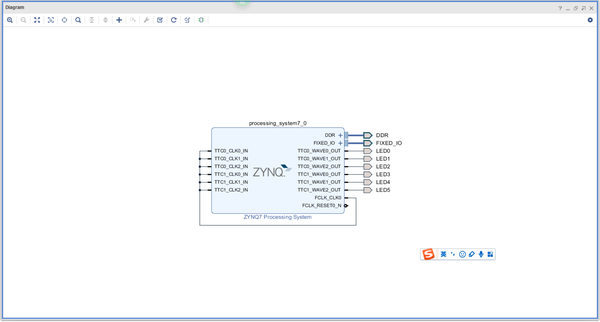
上图是我的BlockDesign,计数主频设定为100KHz,将6路TTC的PWM输出全部接到了LED灯上,然后看看能否按照我的需求闪烁LED灯。现在各自设定闪烁频率为1Hz,2Hz,1Hz,2Hz,1Hz,2Hz在6位LED灯上闪烁,各自用自己的一路TTC定时器控制,不使用中断。
那么,我们看看BSP中的TTC提供了哪些数据结构,常数和API函数供我们使用。
首先最重要的数据结构是:XTtcPs_Config和XTtcPs。他们在xttcps.h中的定义如下:
/**
 * This typedef contains configuration information for the device.
 */
typedef struct {u16 DeviceId;	  /**< Unique ID for device */u32 BaseAddress;  /**< Base address for device */u32 InputClockHz; /**< Input clock frequency */
} XTtcPs_Config;
/**
* The XTtcPs driver instance data. The user is required to allocate a
* variable of this type for each PS timer/counter device in the system. A
* pointer to a variable of this type is then passed to various driver API
* functions.
/
typedef struct {
XTtcPs_Config Config; /< Configuration structure */
u32 IsReady; /< Device is initialized and ready /
} XTtcPs;
接下来是比较重要的几个常数的定义:
/ @name Configuration options

*
- Options for the device. Each of the options is bit field, so more than one
- options can be specified.
- @{
/
#define XTTCPS_OPTION_EXTERNAL_CLK 0x00000001U /< External clock source */
#define XTTCPS_OPTION_CLK_EDGE_NEG 0x00000002U /< Clock on trailing edge for
external clock/
#define XTTCPS_OPTION_INTERVAL_MODE 0x00000004U /< Interval mode */
#define XTTCPS_OPTION_DECREMENT 0x00000008U /< Decrement the counter /
#define XTTCPS_OPTION_MATCH_MODE 0x00000010U /< Match mode */
#define XTTCPS_OPTION_WAVE_DISABLE 0x00000020U /< No waveform output /
#define XTTCPS_OPTION_WAVE_POLARITY 0x00000040U /< Waveform polarity /上面的常数并不是设置到一个寄存器里的设置,实际上这些常数会分别设置到两个寄存器中,具体设置请查阅UG585。
API函数比较多,我们的例子中用到的我全部列出来了:
XTtcPs_CalcIntervalFromFreq() : xttcps.c

XTtcPs_CfgInitialize() : xttcps.c

XTtcPs_LookupConfig() : xttcps.h

XTtcPs_SetMatchValue() : xttcps.c

XTtcPs_SetOptions() : xttcps.h

XTtcPs_SetInterval(): xttcps.h

XTtcPs_SetPrescaler() : xttcps.c

XTtcPs_Start : xttcps.h
接下来是我们的示例代码:
/************************ Include Files *********************************/
#include <stdio.h>
#include <stdlib.h>
#include “xparameters.h”
#include “xstatus.h”
#include “xil_exception.h”
#include “xttcps.h”
#include “xscugic.h”
#include “xil_printf.h”
/************************** Constant Definitions *****************************/
/*
- The following constants map to the XPAR parameters created in the
- xparameters.h file. They are only defined here such that a user can easily
- change all the needed parameters in one place.
/
#define PWM_DELTA_DUTY 50 / PWM 输出方波的占空比*/
/**************************** Type Definitions ******************************/
typedef struct {
u32 OutputHz; / Output frequency /
XInterval Interval; / Interval value /
XInterval Matchval; / Matchval value /
u8 Prescaler; / Prescaler value /
u16 Options; / Option settings */
} TmrCntrSetup;
/***************** Macros (Inline Functions) Definitions *********************/
/************************** Function Prototypes ******************************/
static int SetupPWM(void);
static int SetupTimer(int DeviceID);
/************************** Variable Definitions *****************************/
static XTtcPs TtcPsInst[6]; /* Six timer counters */
static TmrCntrSetup SettingsTable[6] = {
{1, 0, 0, 0, 0},
{2, 0, 0, 0, 0},
{1, 0, 0, 0, 0},
{2, 0, 0, 0, 0},
{1, 0, 0, 0, 0},
{2, 0, 0, 0, 0},};
/***************************************************************************/
/
*
- This function calls the Ttc interrupt example.
- @param None
- @return
-
- XST_SUCCESS to indicate Success -
- XST_FAILURE to indicate Failure. - @note None
*****************************************************************************/
int main(void)
{
int Status;
xil_printf("TTC PWM Example Test\r\n");Status=SetupPWM();
if(Status != XST_SUCCESS) {return Status;
}
while(1);
return XST_SUCCESS;
}
/****************************************************************************/
/**
*
- This function sets up the waveform output timer counter (PWM).
- @param None
- @return XST_SUCCESS if everything sets up well, XST_FAILURE otherwise.
- @note None
*****************************************************************************/
int SetupPWM(void)
{
int Status,i;
TmrCntrSetup *TimerSetup;
XTtcPs *TtcPsPWM;
for(i=0;i<6;i++)
{
TimerSetup = &(SettingsTable[i]);
	/** Set up appropriate options for PWM: interval mode  and* match mode for waveform output.*/TimerSetup->Options |= (XTTCPS_OPTION_INTERVAL_MODE |XTTCPS_OPTION_MATCH_MODE|XTTCPS_OPTION_WAVE_POLARITY|XTTCPS_OPTION_EXTERNAL_CLK|XTTCPS_OPTION_CLK_EDGE_NEG);/** Calling the timer setup routine* 	initialize device* 	set options*/Status = SetupTimer(i);if(Status != XST_SUCCESS) {return Status;}TtcPsPWM = &(TtcPsInst[i]);/** Start the tick timer/counter*/XTtcPs_Start(TtcPsPWM);xil_printf("TTC timer %d is started!\r\n",i);
}
return Status;
}
/****************************************************************************/
/**
*
- This function sets up a timer counter device, using the information in its
- setup structure.
- . initialize device
- . set options
- . set interval and prescaler value for given output frequency.
- @param DeviceID is the unique ID for the device.
- @return XST_SUCCESS if successful, otherwise XST_FAILURE.
- @note None.
*****************************************************************************/
int SetupTimer(int DeviceID)
{
int Status;
XTtcPs_Config *Config;
XTtcPs *Timer;
TmrCntrSetup *TimerSetup;
TimerSetup = &(SettingsTable[DeviceID]);Timer = &(TtcPsInst[DeviceID]);/** Look up the configuration based on the device identifier*/
Config = XTtcPs_LookupConfig(DeviceID);
if (NULL == Config) {return XST_FAILURE;
}/** Initialize the device*/
Status = XTtcPs_CfgInitialize(Timer, Config, Config->BaseAddress);
if (Status != XST_SUCCESS) {return XST_FAILURE;
}
xil_printf("TTC timer %d initialize successfully!\r\n",DeviceID);
/** Set the options*/
XTtcPs_SetOptions(Timer, TimerSetup->Options);/** Timer frequency is preset in the TimerSetup structure,* however, the value is not reflected in its other fields, such as* IntervalValue and PrescalerValue. The following call will map the* frequency to the interval and prescaler values.*/
XTtcPs_CalcIntervalFromFreq(Timer, TimerSetup->OutputHz,&(TimerSetup->Interval), &(TimerSetup->Prescaler));/** Set the interval and prescale*/
TimerSetup->Matchval=TimerSetup->Interval*PWM_DELTA_DUTY/100;
XTtcPs_SetInterval(Timer, TimerSetup->Interval);
XTtcPs_SetPrescaler(Timer, TimerSetup->Prescaler+1);
XTtcPs_SetMatchValue(Timer,0,TimerSetup->Matchval);
return XST_SUCCESS;
}
这篇关于ZYNQ的定时器们(三)TTC定时器到底能干啥?的文章就介绍到这儿,希望我们推荐的文章对编程师们有所帮助!


