本文主要是介绍HDLBits——More Circuits,希望对大家解决编程问题提供一定的参考价值,需要的开发者们随着小编来一起学习吧!
HDLBits——More Circuits
Problem 115 Rule90
Requirement:
Rule90 是一道根据一些有趣的规则来生成一维序列的题目。
规则很简单:一维序列中元素有 1、0 两种状态,分别对应开、关状态。在每个时钟边沿到来时刻,元素的下一个状态为元素相邻两个元素的异或。下表更详细地给出了跳变的规则(可以视为状态转移表),元素下一个状态可以视作输出,输入为元素本身的状态与相应两个相邻元素的当前状态。
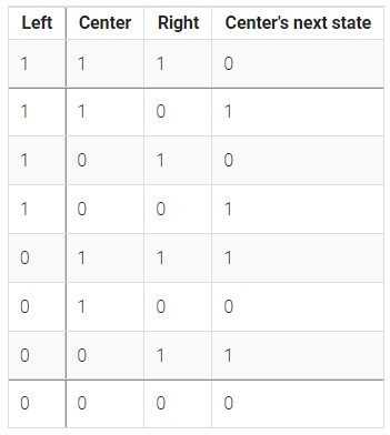
(“Rule90” 这个名字来自表中 “next state 下一状态” 这一栏:01011010是十进制的90。)
对于需要实现的电路,创建一个拥有 512 个元素的序列 (q[511:0]),在每个时钟周期前进一个时间步长。load 信号有效时,序列更新 data 信号值为初始值。假设所有边界的值为 0 (包括 q[-1] 以及 q[512])。
Solution:
module top_module(input clk,input load,input [511:0] data,output [511:0] q ); reg [511:0] q_reg;integer i;always @(posedge clk) beginif(load) beginq_reg<=data;endelse beginq_reg[0] <= q_reg[1];q_reg[511] <= q_reg[510];for (i = 1; i<511 ;i=i+1 ) beginq_reg[i] <= q[i-1]^q[i+1];endendendassign q=q_reg;endmodule
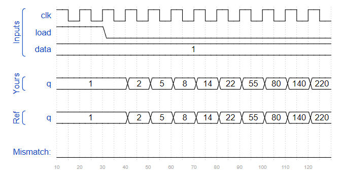
Timing Diagram:
改进:
左右邻居矩阵分别是原矩阵右移或者左移并补零得到。
always @(posedge clk) beginif (load)q <= data; else begin// left rightq <= {1'b0,q[511:1]} ^ {q[510:0], 1'b0} ;endend
Problem 116 Rule110
Requirement:
Rule110 还是一道根据有趣的规则来生成一维序列的题目,比如用于“图灵完备”。
规则:一维序列中元素有 1,0 两种状态,分别对应开,关状态。在每个时钟边沿到来时刻,元素的下一个状态取决于元素本身的状态与前后两个相邻元素的当前状态。下表详细地给出了跳变的规则。
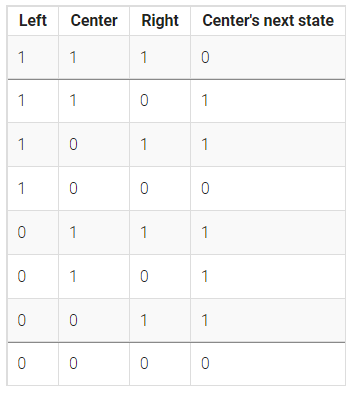
题目中的 Rule110 来自于上表中的 next state 这一列: 01101110= 8’d110。
对于需要实现的电路,创建一个拥有 512 个元素的序列 (q[511:0]),每个时钟周期按照上述规则变换。load 信号有效时,序列更新 data 信号值为初始值。另外假设所有边界的值为 0 (q[-1] q[512])。
Solution:
module top_module(input clk,input load,input [511:0] data,output reg [511:0] q
); always @(posedge clk) beginif(load) beginq<=data;endelse beginq<= ({q[510:0],1'b0}^q) | ({q[510:0],1'b0}&~{1'b0,q[511:1]});endendendmodule
注意:逐位取反是 ~
PS:本题首先需要找出状态转移规则。状态转移表——>真值表——>卡诺图——>逻辑表达式。
真值表对应的是三个输入信号:left,center,right,一个输出信号:next_state。
化简得到:OUT = Center ^ Right + (Center · ~Left )
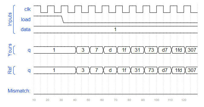
Timing Diagram:
Problem 117 Conwaylift/conway’s game of life 16×16
Requirement:
作为前两题的升级版,本题是一个二维序列生成器。“游戏”是在二维网格单元格上进行的,其中每个单元格要么是 1(活着)要么是 0(死)。
游戏规则如下:元素的下一个状态取决于当前状态九宫格中的 8 个邻居元素中 1 的个数,当邻居有 n 个 1 时:
- 0-1,元素变为 0。
- 2,元素保持不变。
- 3,元素变为 1。
- >=4,元素变为 0。
方便做题起见,本题中的这个二维矩阵设定为 16x16,广义上可以是无限的。为了让事情变得更加有趣,这个 16x16 矩阵的边界进行循环处理,回卷到对边,上边界的上一行为下边界,左边界的左一列为右边界。比如元素 (0,0) 共有 8 个邻居 : (15,1), (15,0), (15,15), (0,1), (0,15), (1,1), (1,0) 以及 (1,15)。
这个 16x16 矩阵表示为 256bit 长度的向量 q,其中 q[15:0] 代表第一行,q[31:16] 代表第二行,以此类推。(HDLBit 支持使用 SystemVerilog,所以你也可以使用二维向量表示这个矩阵。)
- load:在下一个时钟沿将数据加载到 q 中,用于加载初始状态。
- q:游戏的 16x16 当前状态,每个时钟周期更新。
Solution:
module top_module(input clk,input load,input [255:0] data,output reg[255:0] q ); reg [15:0] q_2d [15:0];reg [255:0] q_rt;integer i,j;integer cnt;integer u,d,l,r;always @(*) beginfor (i = 0; i < 16; i = i+1) beginfor (j = 0;j <16 ;j = j+1 ) beginq_2d[i][j] = q[i*16+j];endendfor (i = 0; i < 16; i = i+1) beginfor (j = 0;j <16 ;j = j+1 ) beginu = i==15?0:i+1;d = i==0?15:i-1;r = j==15?0:j+1;l = j==0?15:j-1;cnt = q_2d[u][l] + q_2d[u][j] + q_2d[u][r] +q_2d[i][l] + + q_2d[i][r] +q_2d[d][l] + q_2d[d][j] + q_2d[d][r];case (cnt)2: q_rt[i*16+j] <= q_2d[i][j];3: q_rt[i*16+j] <= 1;default: q_rt[i*16+j] <= 0;endcaseendendendalways @(posedge clk) beginif(load) q<=data;else q<=q_rt;endendmodule
PS:
-
只有0,1时,数 1 的个数直接用加法就行。
-
在一行一行赋值时可以只遍历行,然后
for (i = 0; i < 16; i = i + 1) q_2d[i] = q[16*i +: 16]; -
注意统计邻近 8 个元素的和时写法很妙。
这篇关于HDLBits——More Circuits的文章就介绍到这儿,希望我们推荐的文章对编程师们有所帮助!

![[HDLBits] Simple wire](/front/images/it_default.jpg)


