本文主要是介绍网络工程从头做-1,希望对大家解决编程问题提供一定的参考价值,需要的开发者们随着小编来一起学习吧!
网络工程从头做-1
自下而上,从接入交换机开始网络的配置和规划
实验拓扑:
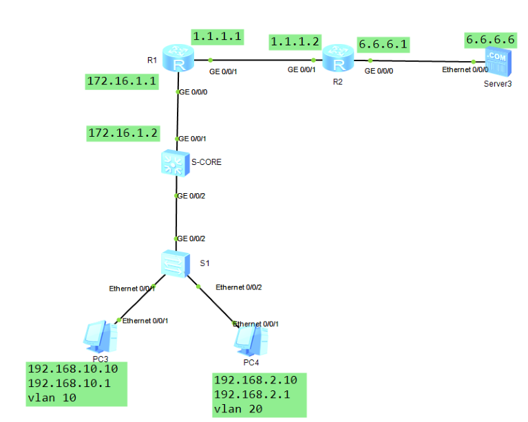
实验步骤:
1.完成基本配置
1.1 PC端IP地址信息配置略
1.2 接入层交换机S1配置
[Huawei]sys S1
[S1]undo in
[S1]vlan b 10 20
[S1]int e0/0/1
[S1-Ethernet0/0/1]p l a
[S1-Ethernet0/0/1]p d v 10
[S1-Ethernet0/0/1]int e0/0/2
[S1-Ethernet0/0/2]p l a
[S1-Ethernet0/0/2]p d v 20
[S1-Ethernet0/0/2]int g0/0/2
[S1-GigabitEthernet0/0/2]p l t
[S1-GigabitEthernet0/0/2]p t a v 10 20
[S1-GigabitEthernet0/0/2]
1.3核心交换机S-CORE配置
sys
[Huawei]sys S-core
[S-core]undo in e
[S-core]vlan b 10 20
Info: This operation may take a few seconds. Please wait for a moment…done.
[S-core]int vlanif 10
[S-core-Vlanif10]ip add 192.168.10.1 24
[S-core-Vlanif10]int vlanif 20
[S-core-Vlanif20]ip add 192.168.2.1 24
[S-core-Vlanif20]int g0/0/2
[S-core-GigabitEthernet0/0/2]p l t
[S-core-GigabitEthernet0/0/2]p t a v 10 20
[S-core-GigabitEthernet0/0/2]
1.3测试PC1与PC2的通信情况
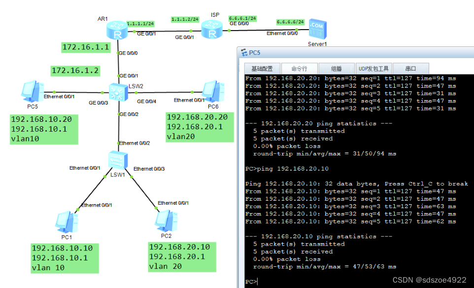
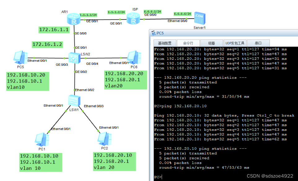
由三层交换技术实现了不同vlan中的PC可以通信,见上图。
小结:相同vlan不同交换机上的通信使用了trunk技术,不同vlan中的PC通过三层交换机上实现了通信。
2.核心交换机S-core的配置
给核心交换机的上联接口g0/0/1配置IP地址172.16.1.2 24
[S-core]vlan 100
[S-core-vlan100]int vlanif 100
[S-core-Vlanif100]ip add 172.16.1.2 24
[S-core-Vlanif100]int g0/0/1
[S-core-GigabitEthernet0/0/1]p l a
[S-core-GigabitEthernet0/0/1]p d v 100
[S-core-GigabitEthernet0/0/1]
3.配置路由R1
sys
[Huawei]sys R1
[R1]undo in e
[R1]int g0/0/0
[R1-GigabitEthernet0/0/0]ip add 172.16.1.1 24
[R1-GigabitEthernet0/0/0]int g0/0/1
[R1-GigabitEthernet0/0/1]ip add 1.1.1.1 24
[R1-GigabitEthernet0/0/1]
----------------------------------------非直连路由的联通问题解决方案-----------------------
4.在核心交换机S-core上配置去外网的路由
[S-core]ip route-static 0.0.0.0 0.0.0.0 172.16.1.1 凡是内网要去外网的所有终端把数据交给路由器内网接口g0/0/0
5.在路由器R1上配置去内网的路由
[R1]ip route-static 192.168.10.0 24 172.16.1.2
[R1]ip route-static 192.168.2.0 24 172.16.1.2
6.测试内网是否可以到达路由器R1
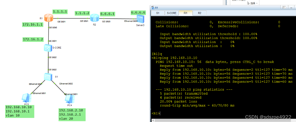
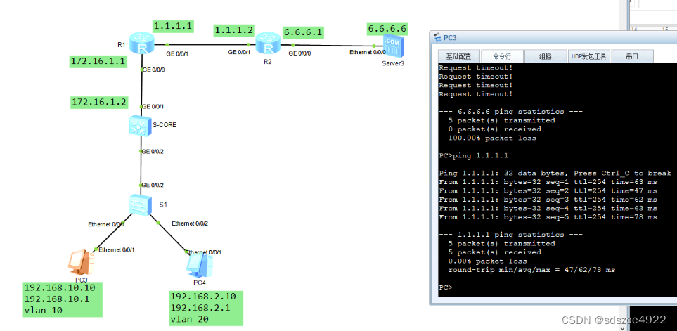
经测试内网PC可以到达路由器R1,但无法到达路由器R2(ISP),更不能到达SERVER6.6.6.6
7.配置运营商的路由器R2
sys
Enter system view, return user view with Ctrl+Z.
[Huawei]sys R2
[R2]undo in e
Info: Information center is disabled.
[R2]int g0/0/1
[R2-GigabitEthernet0/0/1]ip add 1.1.1.2 24
[R2-GigabitEthernet0/0/1]int g0/0/0
[R2-GigabitEthernet0/0/0]ip add 6.6.6.1 24
[R2-GigabitEthernet0/0/0]q
[R2]ip rou
[R2]ip route-s
[R2]ip route-static 0.0.0.0 0.0.0.0 1.1.1.1 所有公网去内网的数据都交给R1公网接口
[R1]ip route-static 0.0.0.0 0.0.0.0 1.1.1.2 所有内网去公网的数据都交给R2运营商ISP
但是:R1能和R2通信但不能和6.6.6.6的服务器通信
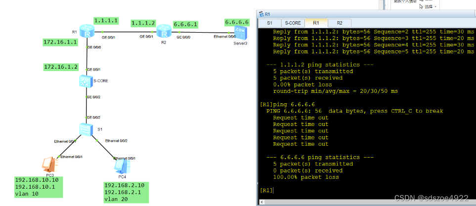
因为私网地址没法直接上公网,需要做NAT地址转换
8.在公司边界路由器R1上做NAT地址转换
[R1]acl 2000
[R1-acl-basic-2000]rule permit source any
[R1-acl-basic-2000]q
[R1]int g0/0/1
[R1-GigabitEthernet0/0/1]nat outbound 2000
[R1-GigabitEthernet0/0/1]
9.测试内网访问外网服务器
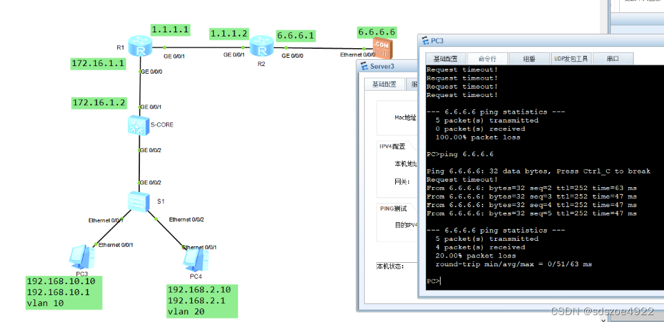
小结:从内网到外网可以通信了。
这篇关于网络工程从头做-1的文章就介绍到这儿,希望我们推荐的文章对编程师们有所帮助!


