本文主要是介绍STM32 TIM1高级定时器配置快速入门,希望对大家解决编程问题提供一定的参考价值,需要的开发者们随着小编来一起学习吧!
layout: post
tags: [STM32]
comments: true
文章目录
- layout: post tags: [STM32] comments: true
- 重点内容
- 时基单元
- 计数模式
重点内容
不管是基于标准库还是直接操作寄存器,因为TIM定时器的功能比较多,这里单纯只从定时器的角度进行学习,这里需要重点关注的地方应该有以下几点:
- 定时器时钟频率的计算;
- 计数器计数的模式,以及一般模式会有哪些应用场景;
- 向上计数
- 向下计数
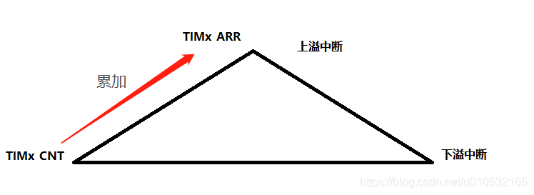
- 中央对齐模式:该模式下需要关注触发中断几种的方式
- 向上溢出中断;
- 向下溢出中断;
- 向上和向下都产生溢出中断;
时基单元
TIM1定时器是一个16位计数器以及相关的自动装载寄存器,比较寄存器,预分频器,可以实现向上,向下,或者向上再向下的计数模式;
基本的时基单元分为:
- 计数器寄存器(
TIMx_CNT) - 预分频器寄存器 (
TIMx_PSC) - 自动装载寄存器 (
TIMx_ARR) - 重复次数寄存器 (
TIMx_RCR)
可以参考STM32参考手册查看相关的寄存器配置说明
下面是TIM功能的整体框图,功能很多,提取了一下计数器的寄存器相应关系;

标准库中,时基单元封装到结构体TIM_TimeBaseInitTypeDef中;
源码如下;
/** * @brief  TIM Time Base Init structure definition* @note   This structure is used with all TIMx except for TIM6 and TIM7.    */typedef struct
{uint16_t TIM_Prescaler;         /*!< Specifies the prescaler value used to                                       divide the TIM clock.This parameter can be a number between 0x0000 and 0xFFFF */uint16_t TIM_CounterMode;       /*!< Specifies the counter mode.This parameter can be a value of @ref TIM_Counter_Mode */uint16_t TIM_Period;            /*!< Specifies the period value to be loaded into the activeAuto-Reload Register at the next update event.This parameter must be a number between 0x0000 and 0xFFFF.  */ uint16_t TIM_ClockDivision;     /*!< Specifies the clock division.This parameter can be a value of @ref TIM_Clock_Division_CKD */uint8_t TIM_RepetitionCounter;  /*!< Specifies the repetition counter value. Each time the RCR downcounterreaches zero, an update event is generated and counting restartsfrom the RCR value (N).This means in PWM mode that (N+1) corresponds to:- the number of PWM periods in edge-aligned mode- the number of half PWM period in center-aligned modeThis parameter must be a number between 0x00 and 0xFF. @note This parameter is valid only for TIM1 and TIM8. */
} TIM_TimeBaseInitTypeDef;
基于标准库的时钟频率计算:
TIMclock = SYSclock * 1/TIM_Prescaler * TIM_Period
/* Compute the value to be set in ARR regiter to generate signal frequency at 17.57 Khz */TimerPeriod = (SystemCoreClock / 17570 ) - 1;/* Time Base configuration */TIM_TimeBaseStructure.TIM_Prescaler = TIM_PSCReloadMode_Update;//TIM_TimeBaseStructure.TIM_CounterMode = TIM_CounterMode_Up;//TIM_TimeBaseStructure.TIM_CounterMode = TIM_CounterMode_CenterAligned1;TIM_TimeBaseStructure.TIM_Period = TimerPeriod;TIM_TimeBaseStructure.TIM_ClockDivision = TIM_CKD_DIV1;TIM_TimeBaseStructure.TIM_RepetitionCounter = 0;TIM_TimeBaseInit(TIM1, &TIM_TimeBaseStructure);
计数模式
- 向上计数模式
TIM_TimeBaseStructure.TIM_CounterMode = TIM_CounterMode_Up - 向下计数模式
TIM_TimeBaseStructure.TIM_CounterMode = TIM_CounterMode_Down - 中央对齐模式
TIM_TimeBaseStructure.TIM_CounterMode = TIM_CounterMode_CenterAligned1
中央对齐模式可以配置TIMx_CR1寄存器的CMS[1:0]位,从而有三种模式可以选择:
| CMS[1:0] | 选择中央对齐模式 (Center-aligned mode selection) |
|---|---|
| 00 | 边沿对齐模式。计数器依据方向位(DIR)向上或向下计数。 |
| 01 | 中央对齐模式1。计数器交替地向上和向下计数。产生下溢中断,配置为输出的通道(TIMx_CCMRx寄存器中CCxS=00)的输出比较中断标志位,只在计数器向下计数时被设置。 |
| 10 | 中央对齐模式2。计数器交替地向上和向下计数。产生上溢中断,配置为输出的通道(TIMx_CCMRx寄存器中CCxS=00)的输出比较中断标志位,只在计数器向上计数时被设置。 |
| 11 | 中央对齐模式3。计数器交替地向上和向下计数。产生下溢和上溢中断,配置为输出的通道(TIMx_CCMRx寄存器中CCxS=00)的输出比较中断标志位,在计数器向上和向下计数时均被设置。 |
具体如下图所示;

这篇关于STM32 TIM1高级定时器配置快速入门的文章就介绍到这儿,希望我们推荐的文章对编程师们有所帮助!


