本文主要是介绍基于MINI2440分析LINUX内核的GPIO子系统分析,希望对大家解决编程问题提供一定的参考价值,需要的开发者们随着小编来一起学习吧!
MINI2440是基于三星S3C2440平台的DEMO板.作为一个SOC,其引脚都有很多复用功能,如一般的GPIO,特定外设的功能引脚,如IIC的CLK引脚.分析其引脚的配置以作笔记.
1.core_initcall(s3c24xx_gpiolib_init):
内核的设计思想,一是喜欢把某个设备打包成结构体;二是尽可能的分离平台相关的代码,使其更具可移植性.
1-1.s3c24xx_gpios:
s3c24xx_gpios是关于MINI2440所有GPIO信息集合.关于MINI2440的GPIO驱动代码入口为:
arch/arm/plat-s3c24xx/gpiolib.c:
core_initcall(s3c24xx_gpiolib_init);
通过函数core_initcall()优先把函数s3c24xx_gpiolib_init()注册进内核:
static __init int s3c24xx_gpiolib_init(void)
{
struct s3c_gpio_chip *chip = s3c24xx_gpios;
int gpn;
for (gpn = 0; gpn < ARRAY_SIZE(s3c24xx_gpios); gpn++, chip++)
s3c_gpiolib_add(chip);
return 0;
}
这里有一个全局变量s3c24xx_gpios是关于S3C24XX平台的GPIO信息集:
struct s3c_gpio_chip s3c24xx_gpios[] = {
[0] = {
.base	= S3C2410_GPACON,
.pm	= __gpio_pm(&s3c_gpio_pm_1bit),
.chip	= {
.base			= S3C2410_GPA(0),
.owner			= THIS_MODULE,
.label			= "GPIOA",
.ngpio			= 24,
.direction_input	= s3c24xx_gpiolib_banka_input,
.direction_output	= s3c24xx_gpiolib_banka_output,
},
},
[1] = {
.base	= S3C2410_GPBCON,
.pm	= __gpio_pm(&s3c_gpio_pm_2bit),
.chip	= {
.base			= S3C2410_GPB(0),
.owner			= THIS_MODULE,
.label			= "GPIOB",
.ngpio			= 16,
},
},
[2] = {
.base	= S3C2410_GPCCON,
.pm	= __gpio_pm(&s3c_gpio_pm_2bit),
.chip	= {
.base			= S3C2410_GPC(0),
.owner			= THIS_MODULE,
.label			= "GPIOC",
.ngpio			= 16,
},
},
[3] = {
.base	= S3C2410_GPDCON,
.pm	= __gpio_pm(&s3c_gpio_pm_2bit),
.chip	= {
.base			= S3C2410_GPD(0),
.owner			= THIS_MODULE,
.label			= "GPIOD",
.ngpio			= 16,
},
},
[4] = {
.base	= S3C2410_GPECON,
.pm	= __gpio_pm(&s3c_gpio_pm_2bit),
.chip	= {
.base			= S3C2410_GPE(0),
.label			= "GPIOE",
.owner			= THIS_MODULE,
.ngpio			= 16,
},
},
[5] = {
.base	= S3C2410_GPFCON,
.pm	= __gpio_pm(&s3c_gpio_pm_2bit),
.chip	= {
.base			= S3C2410_GPF(0),
.owner			= THIS_MODULE,
.label			= "GPIOF",
.ngpio			= 8,
.to_irq			= s3c24xx_gpiolib_bankf_toirq,
},
},
[6] = {
.base	= S3C2410_GPGCON,
.pm	= __gpio_pm(&s3c_gpio_pm_2bit),
.chip	= {
.base			= S3C2410_GPG(0),
.owner			= THIS_MODULE,
.label			= "GPIOG",
.ngpio			= 16,
.to_irq			= s3c24xx_gpiolib_bankg_toirq,
},
}, {
.base	= S3C2410_GPHCON,
.pm	= __gpio_pm(&s3c_gpio_pm_2bit),
.chip	= {
.base			= S3C2410_GPH(0),
.owner			= THIS_MODULE,
.label			= "GPIOH",
.ngpio			= 11,
},
},
};
当我们以后对CPU的引脚的配置(如配置成输入输出、特殊功能),都是路由此结构体s3c24xx_gpios完成.此结构体中的chip域是和内核gpio子系统打交道的"精灵":
struct s3c_gpio_chip {
struct gpio_chip	chip;
struct s3c_gpio_cfg	*config;
struct s3c_gpio_pm	*pm;
void __iomem		*base;
#ifdef CONFIG_PM
u32			pm_save[4];
#endif
};
这里根据平台相关的GPIO信息s3c24xx_gpios去初始化内核gpio子系统需要的gpio_chip,然后将他推送进内核gpio子系统.
1-2.struct gpio_chip:
struct gpio_chip {
const char		*label;
struct device		*dev;
struct module		*owner;
int			(*request)(struct gpio_chip *chip,
unsigned offset);
void			(*free)(struct gpio_chip *chip,
unsigned offset);
int			(*direction_input)(struct gpio_chip *chip,
unsigned offset);
int			(*get)(struct gpio_chip *chip,
unsigned offset);
int			(*direction_output)(struct gpio_chip *chip,
unsigned offset, int value);
void			(*set)(struct gpio_chip *chip,
unsigned offset, int value);
int			(*to_irq)(struct gpio_chip *chip,
unsigned offset);
void			(*dbg_show)(struct seq_file *s,
struct gpio_chip *chip);
int			base;
u16			ngpio;
char			**names;
unsigned		can_sleep:1;
unsigned		exported:1;
};
此结构体是和内核GPIO子系统的关键数据结构,里面包括判断gpio是否被占用,配置成输入还是输出,配置成中断等,全部被记录在这个结构体里面.
2.s3c_gpiolib_add(chip):
上述分析了平台相关的结构体s3c24xx_gpios和gpio_chip的关系,并根据平台相关的s3c24xx_gpios去初始化gpio_chip.在上述s3c24xx_gpiolib_init()函数在,见下面代码:
	for (gpn = 0; gpn < ARRAY_SIZE(s3c24xx_gpios); gpn++, chip++)
s3c_gpiolib_add(chip);
核心函数为s3c_gpiolib_add():
__init void s3c_gpiolib_add(struct s3c_gpio_chip *chip)
{
struct gpio_chip *gc = &chip->chip;
int ret;
BUG_ON(!chip->base);
BUG_ON(!gc->label);
BUG_ON(!gc->ngpio);
if (!gc->direction_input)
gc->direction_input = s3c_gpiolib_input;
if (!gc->direction_output)
gc->direction_output = s3c_gpiolib_output;
if (!gc->set)
gc->set = s3c_gpiolib_set;
if (!gc->get)
gc->get = s3c_gpiolib_get;
#ifdef CONFIG_PM
if (chip->pm != NULL) {
if (!chip->pm->save || !chip->pm->resume)
printk(KERN_ERR "gpio: %s has missing PM functions\n",
gc->label);
} else
printk(KERN_ERR "gpio: %s has no PM function\n", gc->label);
#endif
/* gpiochip_add() prints own failure message on error. */
ret = gpiochip_add(gc);
if (ret >= 0)
s3c_gpiolib_track(chip);
}
2-1.void s3c_gpiolib_add(struct s3c_gpio_chip *chip):
在此函数中,一开始便用平台相关的s3c24xx_gpios来完善内核GPIO子系统的关键数据结构gpio_chip:
	struct gpio_chip *gc = &chip->chip;
int ret;
BUG_ON(!chip->base);
BUG_ON(!gc->label);
BUG_ON(!gc->ngpio);
if (!gc->direction_input)
gc->direction_input = s3c_gpiolib_input;
if (!gc->direction_output)
gc->direction_output = s3c_gpiolib_output;
if (!gc->set)
gc->set = s3c_gpiolib_set;
if (!gc->get)
gc->get = s3c_gpiolib_get;
例如把常用的gpio操作对此gpio_chip进行封装,比如把输入配置成s3c_gpiolib_input;把输出配置成s3c_gpiolib_output;获取gpio状态初始化为s3c_gpiolib_get;设置gpio状态初始化为s3c_gpiolib_set.
2-2.int gpiochip_add(struct gpio_chip *chip):
在函数s3c_gpiolib_add()在,见下面代码:
ret = gpiochip_add(gc);此函数位于drivers/gpio/gpiolib.c目录下,可见,是内核GPIO子系统公共代码,与具体平台无关:
/**
* gpiochip_add() - register a gpio_chip
* @chip: the chip to register, with chip->base initialized
* Context: potentially before irqs or kmalloc will work
*
* Returns a negative errno if the chip can't be registered, such as
* because the chip->base is invalid or already associated with a
* different chip.  Otherwise it returns zero as a success code.
*
* When gpiochip_add() is called very early during boot, so that GPIOs
* can be freely used, the chip->dev device must be registered before
* the gpio framework's arch_initcall().  Otherwise sysfs initialization
* for GPIOs will fail rudely.
*
* If chip->base is negative, this requests dynamic assignment of
* a range of valid GPIOs.
*/
int gpiochip_add(struct gpio_chip *chip)
{
unsigned long	flags;
int		status = 0;
unsigned	id;
int		base = chip->base;
if ((!gpio_is_valid(base) || !gpio_is_valid(base + chip->ngpio - 1))
&& base >= 0) {
status = -EINVAL;
goto fail;
}
spin_lock_irqsave(&gpio_lock, flags);
if (base < 0) {
base = gpiochip_find_base(chip->ngpio);
if (base < 0) {
status = base;
goto unlock;
}
chip->base = base;
}
/* these GPIO numbers must not be managed by another gpio_chip */
for (id = base; id < base + chip->ngpio; id++) {
if (gpio_desc[id].chip != NULL) {
status = -EBUSY;
break;
}
}
if (status == 0) {
for (id = base; id < base + chip->ngpio; id++) {
gpio_desc[id].chip = chip;
/* REVISIT:  most hardware initializes GPIOs as
* inputs (often with pullups enabled) so power
* usage is minimized.  Linux code should set the
* gpio direction first thing; but until it does,
* we may expose the wrong direction in sysfs.
*/
gpio_desc[id].flags = !chip->direction_input
? (1 << FLAG_IS_OUT)
: 0;
}
}
unlock:
spin_unlock_irqrestore(&gpio_lock, flags);
if (status == 0)
status = gpiochip_export(chip);
fail:
/* failures here can mean systems won't boot... */
if (status)
pr_err("gpiochip_add: gpios %d..%d (%s) not registered\n",
chip->base, chip->base + chip->ngpio - 1,
chip->label ? : "generic");
return status;
}
在这里出现一个很重要的结构体struct gpio_desc.是定义于drivers/gpio/gpiolib.c文件中的一个静态全局变量:
static struct gpio_desc gpio_desc[ARCH_NR_GPIOS];
这个静态全局变量的意义在于以后用到具体操作哪个GPIO的时候,均需要从这个数组找到相应的gpio_chip,然后根据相应的gpio_chip实现具体的gpio的个性化操作.下面来看如何对此数组进行初始化:
		for (id = base; id < base + chip->ngpio; id++) {
gpio_desc[id].chip = chip;
/* REVISIT:  most hardware initializes GPIOs as
* inputs (often with pullups enabled) so power
* usage is minimized.  Linux code should set the
* gpio direction first thing; but until it does,
* we may expose the wrong direction in sysfs.
*/
gpio_desc[id].flags = !chip->direction_input
? (1 << FLAG_IS_OUT)
: 0;
}
可见,数组gpio_desc每个元素都表征一个pin脚.看一下变量base的赋值过程:
int base = chip->base;
其中,chip即为函数int gpiochip_add(struct gpio_chip *chip)的参数.追踪一下源码便知是s3c24xx_gpios中的chip域.如:
		.chip	= {
.base			= S3C2410_GPA(0),
.owner			= THIS_MODULE,
.label			= "GPIOA",
.ngpio			= 24,
.direction_input	= s3c24xx_gpiolib_banka_input,
.direction_output	= s3c24xx_gpiolib_banka_output,
}
.chip	= {
.base			= S3C2410_GPB(0),
.owner			= THIS_MODULE,
.label			= "GPIOB",
.ngpio			= 16,
}
... ...;
此时数组gpio_desc记录的便是平台相关的s3c24xx_gpios的chip域.
下面以S3C2410_GPA(0)为例分析一下其base域:
.base			= S3C2410_GPA(0)
#define S3C2410_GPA(_nr)	(S3C2410_GPIO_A_START + (_nr))
enum s3c_gpio_number {
S3C2410_GPIO_A_START = 0,
S3C2410_GPIO_B_START = S3C2410_GPIO_NEXT(S3C2410_GPIO_A),
S3C2410_GPIO_C_START = S3C2410_GPIO_NEXT(S3C2410_GPIO_B),
S3C2410_GPIO_D_START = S3C2410_GPIO_NEXT(S3C2410_GPIO_C),
S3C2410_GPIO_E_START = S3C2410_GPIO_NEXT(S3C2410_GPIO_D),
S3C2410_GPIO_F_START = S3C2410_GPIO_NEXT(S3C2410_GPIO_E),
S3C2410_GPIO_G_START = S3C2410_GPIO_NEXT(S3C2410_GPIO_F),
S3C2410_GPIO_H_START = S3C2410_GPIO_NEXT(S3C2410_GPIO_G),
};
#define S3C2410_GPIO_NEXT(__gpio) \
((__gpio##_START) + (__gpio##_NR) + CONFIG_S3C_GPIO_SPACE + 0)
#if CONFIG_S3C_GPIO_SPACE != 0
#error CONFIG_S3C_GPIO_SPACE cannot be zero at the moment
#endif
这里的CONFIG_S3C_GPIO_SPAC是内核配置选项
CONFIG_S3C_GPIO_SPACE = 0
由此可以推知:
S3C2410_GPIO_A_START = 0
S3C2410_GPIO_B_START = S3C2410_GPIO_A_START + S3C2410_GPIO_A_NR + 0 + 0 = 0 + S3C2410_GPIO_A_NR + 0 + 0
其中,
#define S3C2410_GPIO_A_NR	(32)
所以,
S3C2410_GPIO_B_START = 0 + 32 + 0 + 0 = 32
因此,
对于gpio_chip_GPIOA:
.base = S3C2410_GPA(0) = 	S3C2410_GPIO_A_START + 0 = 0 + 0 = 0
对于gpio_chip_GPIOB:
.base	= S3C2410_GPB(0) =  S3C2410_GPIO_B_START + 0 = 32 + 0 = 32
3.具体实例
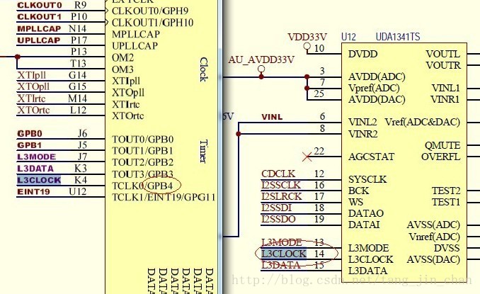
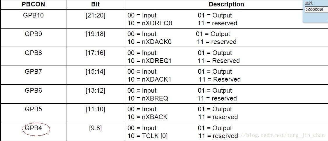
我们知道一片SOC的GPIO引脚一般复用了特殊功能,如时钟引脚等.要配置某个引脚为某功能,需要对控制某引脚的寄存器.下面以MINI2440搭载的UDA1341TS音频IC为例看其相关引脚是如何配置成UDA1341TS所需要的功能引脚.比如UDA1341TS的时钟引脚是连接到S3C2440X的GPB4引脚.如下图所示:
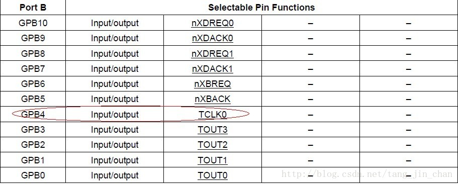
根据S3C2440的数据手册.如下:
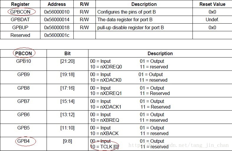
相关GPIO功能寄存器由S3C2440的数据手册如下:
下面看一下MINI2440平台的内核是如何配置一个GPIO的.
3-1.UDA1341TS设备端:
static struct platform_device mini2440_audio __initdata = {
.name		= "s3c24xx_uda134x",
.id		= 0,
.dev		= {
.platform_data	= &mini2440_audio_pins,
},
};
其中,platform_data存放的就是相关GPIO的的信息.如下:
/* AUDIO */
static struct s3c24xx_uda134x_platform_data mini2440_audio_pins __initdata = {
.l3_clk = S3C2410_GPB(4),
.l3_mode = S3C2410_GPB(2),
.l3_data = S3C2410_GPB(3),
.model = UDA134X_UDA1341
};
以l3_clk为例,S3C2410_GPB(4)根据上述的2-2可知,l3_clk等于36.
3-2.UDA1341TS驱动端:
关于设备端和驱动端如何匹配,可参看网络一些资料.大体流程如下:
sound/soc/s3c24xx/s3c24xx_uda134x.c
module_init(s3c24xx_uda134x_init);
->
static int __init s3c24xx_uda134x_init(void)
{
return platform_driver_register(&s3c24xx_uda134x_driver);
}
->
static int s3c24xx_uda134x_probe(struct platform_device *pdev)
关于l3_clk的相关代码如下:
	if (s3c24xx_uda134x_setup_pin(s3c24xx_uda134x_l3_pins->l3_clk,
"clk") < 0) {
gpio_free(s3c24xx_uda134x_l3_pins->l3_data);
return -EBUSY;
}
由3-1设备端可知,s3c24xx_uda134x_l3_pins->l3_clk = 36.展开函数static int s3c24xx_uda134x_setup_pin(int pin, char *fun):
static int s3c24xx_uda134x_setup_pin(int pin, char *fun)
{
if (gpio_request(pin, "s3c24xx_uda134x") < 0) {
printk(KERN_ERR "S3C24XX_UDA134X SoC Audio: "
"l3 %s pin already in use", fun);
return -EBUSY;
}
gpio_direction_output(pin, 0);
return 0;
}
根据上面的分析,明显这里的参数pin = 36.函数gpio_direction_output()意为把此pin脚配置成输出.展开函数gpio_direction_output()提取相关代码:
int gpio_direction_output(unsigned gpio, int value)
{
struct gpio_chip	*chip;
struct gpio_desc	*desc = &gpio_desc[gpio];
chip = desc->chip;
gpio -= chip->base;
status = chip->direction_output(chip, gpio, value);
}
这里根据传入参数可知,gpio = 36,value = 0.其中下面的语句代码:
struct gpio_desc *desc = &gpio_desc[gpio];
在上述的2-2.int gpiochip_add(struct gpio_chip *chip)函数分析中,曾对全局数组gpio_desc进行初始化.如下:
		for (id = base; id < base + chip->ngpio; id++) {
gpio_desc[id].chip = chip;
另外,在1-1函数s3c24xx_gpiolib_init()中见下面代码:
	for (gpn = 0; gpn < ARRAY_SIZE(s3c24xx_gpios); gpn++, chip++)
s3c_gpiolib_add(chip);
GPB(4)是落在了gpio_chip_GPIOB.其base域等于32.这里索引的gpio = 36.因此,提取的是gpio_chip_GPIOB的第(36 - 32 = 4,数组从0开始)5个pin相应的结构体.即:
		.chip	= {
.base			= S3C2410_GPB(0),
.owner			= THIS_MODULE,
.label			= "GPIOB",
.ngpio			= 16,
}
下面代码计算GPB(4)相对于GPIOB组的偏移量:
gpio -= chip->base;此时,gpio = 36 - 32 = 4.然后回调gpio_chip的direction_output()函数.回到上述2-1函数s3c_gpiolib_add()见下面代码:
	if (!gc->direction_input)
gc->direction_input = s3c_gpiolib_input;
if (!gc->direction_output)
gc->direction_output = s3c_gpiolib_output;
可见,这里的 status = chip->direction_output(chip, gpio, value);实际调用的是s3c_gpiolib_output.而其三个参数分别为:chip = &gpio_desc[36]->chip;gpio = 4;value = 0.
3-3.static int s3c_gpiolib_output(struct gpio_chip *chip,unsigned offset, int value):
虽然走进了内核的gpio子系统,现在又回归到也必须回归到平台相关的操作:
static int s3c_gpiolib_output(struct gpio_chip *chip,
unsigned offset, int value)
{
struct s3c_gpio_chip *ourchip = to_s3c_gpio(chip);
void __iomem *base = ourchip->base;
unsigned long flags;
unsigned long dat;
unsigned long con;
local_irq_save(flags);
dat = __raw_readl(base + 0x04);
dat &= ~(1 << offset);
if (value)
dat |= 1 << offset;
__raw_writel(dat, base + 0x04);
con = __raw_readl(base + 0x00);
con &= ~(3 << (offset * 2));
con |= 1 << (offset * 2);
__raw_writel(con, base + 0x00);
__raw_writel(dat, base + 0x04);
local_irq_restore(flags);
return 0;
}
第一条语句获取的是平台相关的s3c_gpio_chip而并且内核GPIO子系统的gpio_chip.但是它是通过我们的gpio_chip提取的.明显,这里是s3c24xx_gpios.gpio_desc[36]根据上面的分析,位于s3c24xx_gpios[1],即:
struct s3c_gpio_chip s3c24xx_gpios[] =
{
... ...;
[1] = {
.base	= S3C2410_GPBCON,
.pm	= __gpio_pm(&s3c_gpio_pm_2bit),
.chip	= {
.base			= S3C2410_GPB(0),
.owner			= THIS_MODULE,
.label			= "GPIOB",
.ngpio			= 16,
},
},
... ...;
}
这里主要弄明白宏S3C2410_GPBCON如何对应上S3C2440的数据手册即可:
.base	= S3C2410_GPBCON,
#define S3C2410_GPBCON	   S3C2410_GPIOREG(0x10)
#define S3C2410_GPIOREG(x) ((x) + S3C24XX_VA_GPIO)
#define S3C24XX_VA_GPIO	   ((S3C24XX_PA_GPIO - S3C24XX_PA_UART) + S3C24XX_VA_UART)
#define S3C24XX_PA_GPIO     S3C2410_PA_GPIO
#define S3C2410_PA_GPIO	   (0x56000000)
#define S3C24XX_PA_UART     S3C2410_PA_UART
#define S3C2410_PA_UART	   (0x50000000)
#define S3C24XX_VA_UART	   S3C_VA_UART
#define S3C_VA_UART	S3C_ADDR(0x01000000)	/* UART */
#define S3C_ADDR(x)	((void __iomem __force *)S3C_ADDR_BASE + (x))
#define S3C_ADDR_BASE	(0xF4000000)
因此,得出下面结论:
.base = S3C2410_GPBCON
= S3C2410_GPIOREG(0x10)
= 10 + S3C24XX_VA_GPIO
= 10 + (0x56000000 - 0x50000000 + (0xF4000000 + 0x01000000))
= 10 + (0x06000000 + 0xF5000000)
= 10 + 0xFB000000
= 0xFB000010
其中这里地址值0xFB000010是GPBCON寄存器的虚拟地址.操作这个地址值即为操作GPBCON寄存器的值.当然这归功于MMU[注:MMU另外分析].下面可以进行猜测此MMU
是线性映射的:
#define S3C2410_PA_UART (0x50000000)
#define S3C24XX_VA_UART (0xF5000000)
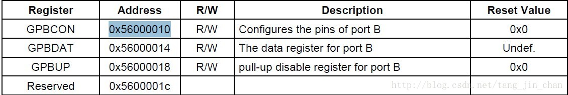
S3C24XX_VA_UART - S3C2410_PA_UART = 0xA5000000将地址:0xFB000010 - 0xA5000000 = 0x56000010
对照S3C2440的数据手册:
函数s3c_gpiolib_output()接下来的代码便是找到相关的pin脚的寄存器进行配置.如下:
那么,对于配置成输出,到底是纯粹的GPIO电平pin输出还是作为特殊功能pin呢?见函数s3c_gpiolib_output()下面代码:
	dat = __raw_readl(base + 0x04);
dat &= ~(1 << offset);
if (value)
dat |= 1 << offset;
__raw_writel(dat, base + 0x04);
这是根据函数
static int s3c_gpiolib_output(struct gpio_chip *chip,unsigned offset, int value) 最后一个参数value来区分的,如果value = 0即为特殊功能pin;若value = 1即为普通output pin.可代入验证.当然,这得益于S3C2440的pin脚只有三种功能,而且输入输出还有特殊功能pin是固定的配置值.可见,这代码的可移植性及可读性并不强.
这篇关于基于MINI2440分析LINUX内核的GPIO子系统分析的文章就介绍到这儿,希望我们推荐的文章对编程师们有所帮助!


