本文主要是介绍[移动通讯]【Carrier Aggregation-10】【 Radio Resource Control (RRC) Aspects】,希望对大家解决编程问题提供一定的参考价值,需要的开发者们随着小编来一起学习吧!
前言:
参考《4G/LTE - LTE Advanced》
Carrier Aggregation is a special form of LTE technology that enables UE and Network to use more than one carrier frequencies. Actually this is not a new concept in LTE. You might have used/heard Dual Carrier in WCDMA HSDPA (HSDPA DC) or similar mode in WiFi
目录:
- Initial Motivation for Carrier Aggregation
- Initial Deployment
- Overview of Carrier Allocation and Network Architecture
- Layer 2 Structure of Carrier Aggregation
- What kind of Aggregated Carrier (Carrier Combination) is possible ?
- E-UTRA CA configurations and bandwidth combination sets defined for intra-band contiguous CA
- E-UTRA CA configurations and bandwidth combination sets defined for non-contiguous intra-band CA (with two sub-blocks)
- E-UTRA CA configurations and bandwidth combination sets defined for inter-band CA
- Test Frequency Table
6 Determining Channel Spacing for Intra-band Contiguous CA
7 How a Network know if a UE support Carrier Aggregation ?
8 Overall Sequence of Adding a Second Carrier
9 Evolution path of Carrier Aggregation / Possible Test Plan
一 Initial Motivation for Carrier Aggregation
You may be hearing more and more about LTE Advanced these days (approaching the end of 2012) and you may think "Do we really need such a huge bandwidth ? Is the current LTE BW not enough ? Do we have all the technologies mature enough for LTE Advanced Implementation ?"
To see the mature implementation of LTE advanced network or mobile phone, you should get firm "YES" to following quesitons first.
Is there any major LTE Network Operators who has strong willingness to deploy LTE Advanced Network(Feature) ?
Are all those components (especially baseband chipsets and RF devices) for LTE advanced device available and mature in the market ?
Are there any test equipment which are providing the test capability for the device ?
As of the end of 2012, I don't think I have firm "YES" to any of these questions. But I am hearing that a couple of LTE network operators will deploy LTE Advanced feature in very near future and some operators has already supported the feature. I think this is true, but the LTE advanced they talk about at this point is not the full fledged technology and it is mainly about Carrier Aggregation.
Does this mean that they already feel the current 20 Mhz LTE bandwidth is not enough ? As far as I know, it is not because of this. Even though the current LTE supports 20 Mhz BW in max, there are only a few network operators who is certified for such a wide bandwidth. The most common bandwidth that network operators has for LTE is 10 Mhz, which means they are not fully utilizing the LTE capability in terms of bandwidth. This is not because of technical restriction, it is purely because of licensing issues for the allocated bandwidth.
Even though there is not many Network Operators who has 20 Mhz BW, there are some network operators who has license multiple band (e.g, two separated 10 Mhz BW and two or more 5 Mhz BW). These network operators wants to combine those multiple bands to achieve wide BW (in most case 20 Mhz BW) LTE. It is the initial motivation for LTE Advanced for now and I don't think we will see the fully grown LTE advanced technology in any time soon. We still have a lot of things to be done even for the initial LTE (Release 8 LTE) and this maturing process would take a couple of more years. LTE Advanced will be introduced gradually in parallele to Release 8 LTE, but initial introduction of LTE advanced would be more about "Marketing motivation" rather than "Technical motivation".
市场动机:运营商离散的频谱资源,需要充分利用,提高带宽。
二 Initial Deployment
You may heard from other sources or will see in this page a lot of fancy stories about LTE advanced (like the aggregation of 5 carriers with 20 Mhz BW each, 8 x 8 DL MIMO, 4 x 4 UL MIMO, 1G Data Rate etc). But as I mentioned above, the reality would not be as fancy as you may expect. As of Jan, 2013. The only type of deployment I am hearing that some network operators would deploy is as follows :
i) 2 DL Carriers (mostly 10 Mhz BW each, Inter band)
ii) NO UL Subcarriers
CA 聚合的三种方式
Intra-band continues
Intra-band non-continues
Intre-band
Even this simple configuration there are many things to consider and following is some of the list.
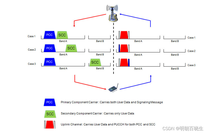
Q1: What kind of data you would carry on the primary and secondary DL carrier ?
Q2 Definately both channel can carry PDSCH.
Q3 How about PDCCH ?
Q4: Would both DL carry each of its own PDCCH seprately ?
Q5 or Primary DL Carrier would carry PDCCH for both carrier and the secondary carrier carry only PDSCH ?.
Q6 Both options are possible and it is upto network implementation.
Q7 How kind of data you would carry on UL carrier ?
: You may think there would be no differences in UL carrier if UL does not support multi carrier as in the initial deployment,
but it would not be true. There would be no differences in terms of PUSCH,
but how about PUCCH? Since UE is getting PDSCHs from two separate carriers, there should be questions of how to send HARQ ACK/NACK for
each of the PDSCH. Should UE send separate PUCCHs(HARQ ACK/NACK for each DL carriers) or single PUCCH carrying the HARQ ACK/NACK for both channels.
Both options are possible in terms of Rel 9/Rel 10 specification, but it is higher possibility to use a single PUCCH for carrying HARQ ACK/NACK for both DL carriers.
It means that we will have new PUCCH format for this situation.
Q8 How to handle PRACH ?
: Since UE can have possibility of send Uplink to two different carrier and can receive the data from two separate carrier.
Possible channels for PRACH procedure can be diverse as shown below.
PRACH via Primary Carrier and RAR via Primary Carrier
PRACH via Primary Carrier and RAR via Secondary Carrier
PRACH via Secondary and RAR via Secondary Carrier
and couple of others.
But I guess the first option would be the best candidate since it is easy and is the same as Rel 8 method we are currently using.
How to handle handover with dual carrier ?
For this, we may also have easy option or tricky option.
Tricky option would be to handover the two carrier without any modification from one cell (source cell) to another (destination cell).
but this will cause a lot of issues if it is not very carefully implemented.
Easy option would be to remove the secondary DL channel before handover and then perform handover and configure the secondary channel
in the destination cell.
Of course, it is highly probable to take an easy option for initial deployment.
三 Overview of Carrier Allocation and Network Architecture
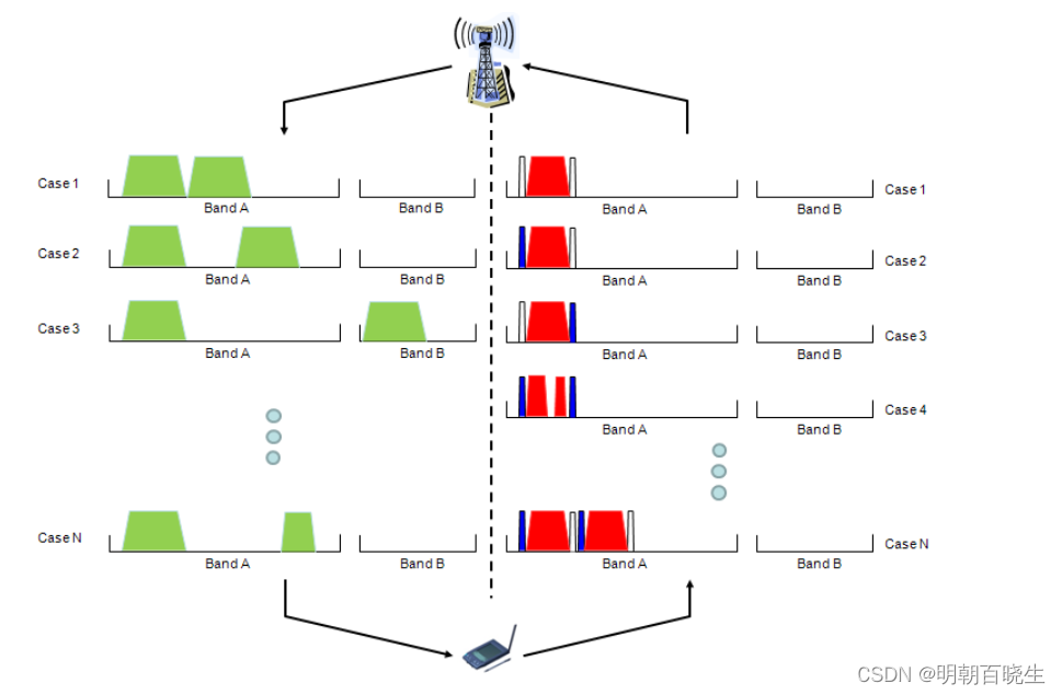
One of the most important/critical feature in LTE Advanced is that we use multiple carriers in downlink and possible in uplink as well.
It may sound simple to use multiple carriers, but in reality, with the introduction of multiple carrier all the possible carrier/resource allocation
in uplink and downlink has such a huge combinations as shown below.
This is not just a graphicaly complication -:).
Just by looking at this illustration, a lot of questions would be boggling in your mind.
How to allocated resources (number of RBs) in control channel ?
Do we have to have separate HARQ process for each carrier ?
or single-aggregated HARQ for the multiple carrier ?
What about Uplink side ? How can I schedule the resource for Multiple SC-FDMA (Clustered SC-FDMA) ? etc... These are the topics I have to add later.. For now,
just enjoy the illustration and use your imagination for all of these questions.
Trying to get the solution based on your imagination would greatly help you to understand 3GPP specification.
This is a kind of motivation step for the new study.
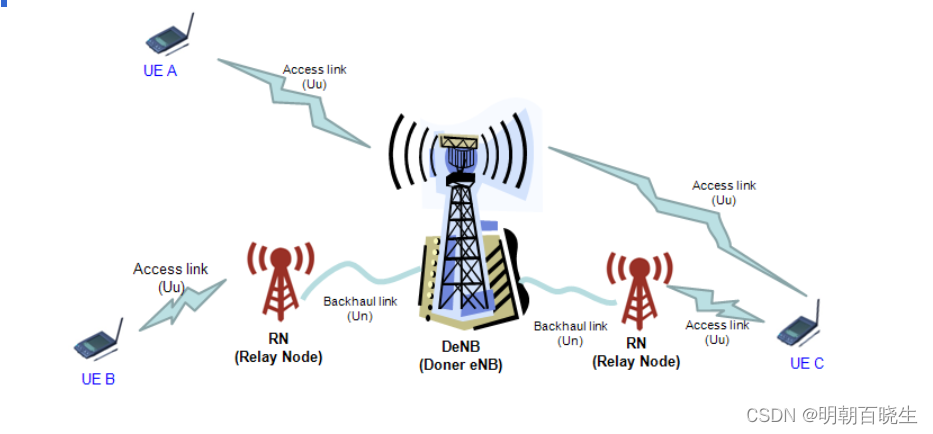
Another aspect of LTE Advanced is network architecture side. One of the key modification of LTE advanced is 'Relay Node' to improve data communication
especially on cell boundary and increase cell coverage. Again, I just put the illustrations and I would like you to use your imagination to find the answers
to the questions popping up in your mind. Do we need any RRC message or Information element to handle this Relay Node ?
How a UE handle the situation as shown for UE C in the following illustration.
This UE is getting the similar strength of signals both from eNodeB and Relay Node.
Would it be possible to handover between two Relay Nodes ? Would the Relay Node have the same RF capability as eNB ?
Would this Relay Node get involved in L1/PHY scheduling as well ? etc.
四 Layer 2 Structure of Carrier Aggregation
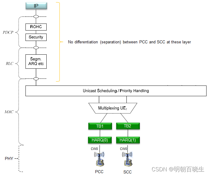
Many people asked me "Is there any way to direct a specific IP packet to PCC (Mirmary Component Carrier) and another specific IP packet to SCC (Secondary Component Carrier) ?".
The Answer is 'No'.
You may understand why the answer is 'NO' from L2 structure of 3GPP 36.300 as shown below (This figure may look a little too complicated. You will find clearer figure after this). As you may notice here, Carrier Layer Aggregation is MAC-PHY layer concept and it is not applied to higher layer.
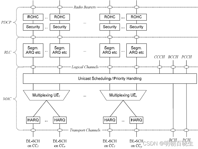
For clarity, let's suppose a case of a Carrier Aggregation with 2 CC(Component Carrier) and each carrier support SISO. Following is overal data path from IP to Physical layer. As you see, from IP through RLC, there is no separate path between PCC and SCC.
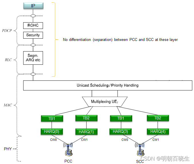
For clarity, let's suppose a case of a Carrier Aggregation with 2 CC(Component Carrier) and each carrier support MIMO. Following is overall data path from IP to Physical layer. As you see, from IP through RLC, there is no separate path between PCC and SCC.
| item | cate |
| B111 LTE LL1 Rx Agc Log:Rx AGC log packet for both PCC and SCC individually | individually |
| B139 LTE LL1 PUSCH Tx Report:Number of ACK/NACK bits is 4. In the example below, the UE sends ACKS for both DL MIMO streams on PCC and SCC | pcc |
| B173 LTE PDSCH Stat Indication:Serving cell index indicates the respective grant on PCell and SCell.Each CC has an independent HARQ process i.e., 8 HARQ IDs per CC. | individually |
| B18A LTE ML1 RLM Report - RLM BLER/SNR is calculated only on PCell. | pcc |
| B130 LTE LL1 PDCCH Decoding Result .UE decodes PDCCH on both SCC and PCC | pcc |
B193 LTE ML1 Idle Serving Cell Meas Response Shows both PCell and SCell measurements | pcc |
五 What kind of Aggregated Carrier (Carrier Combination) is possible ?
Now the question you may ask is how can I know which band combination of bands a UE support in terms of Carrier Aggregation ?
It is also supposed to be reported to network by the UE via UE Capability Information message. Followings are some of the possible IEs a UE may use depending on its release status.
RF-Parameters-v1020 ::= SEQUENCE {
supportedBandCombination-r10 SupportedBandCombination-r10
}
RF-Parameters-v1090 ::= SEQUENCE {
supportedBandCombination-v1090 SupportedBandCombination-v1090 OPTIONAL
}
RF-Parameters-v1130 ::= SEQUENCE {
supportedBandCombination-v1130 SupportedBandCombination-v1130 OPTIONAL
}
The definition of these IE is described as below in 36.331. Generally it sounds OK.. but it is not very clear to me if I go into one step deeper. For example, this definition does not clearly explain on which item in the list can be a PCC (Primary Component Carrier) and which should be SCC (Secondary Component Carrier). As far as I know, there is no priority of these items in terms of determining PCC/SCC, meaning either one should be allowed to be PCC depending on situation. But you may see some UE that allows only specific PCC/SCC mapping.
bandCombinationListEUTRA : One entry corresponding to each supported band combination listed in the same order as in supportedBandCombination.
BandCombinationParameters-v1090 : If included, the UE shall include the same number of entries, and listed in the same order, as in BandCombinationParameters-r10.
BandCombinationParameters-v1130 :The field is applicable to each supported CA bandwidth class combination (i.e. CA configuration in TS 36.101 Section 5.6A.1 indicated in the corresponding band combination
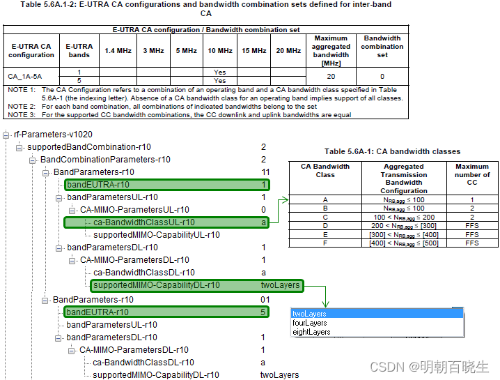
One example of Carrier Combination information in UE Capability Information is as follows. This example shows the UE allows Carrier Aggregation between band 4 and band 17.
nonCriticalExtension
rf-Parameters-v1020
supportedBandCombination-r10: 1 item
Item 0
BandCombinationParameters-r10: 2 items
Item 0
BandParameters-r10
bandEUTRA-r10: 4
bandParametersUL-r10: 1 item
Item 0
CA-MIMO-ParametersUL-r10
ca-BandwidthClassUL-r10: a
bandParametersDL-r10: 1 item
Item 0
CA-MIMO-ParametersDL-r10
ca-BandwidthClassDL-r10: a
supportedMIMO-CapabilityDL-r10: twoLayers
Item 1
BandParameters-r10
bandEUTRA-r10: 17
bandParametersDL-r10: 1 item
Item 0
CA-MIMO-ParametersDL-r10
ca-BandwidthClassDL-r10: a
supportedMIMO-CapabilityDL-r10: twoLayers
Following Table from 36.101 V11.7.0 (2014-03) shows all the possible (allowed) band combination of inter-band CA case. This list is likely to get extended as time goes on. So try to refer to latest spec. I just put inter-band case since I see only inter-band CA which is really deployed as of now (Apr 2014). If you are interested in intra-band CA, refer to Table 5.6A.1-1, Table 5.6A.1-3 in 36.101.
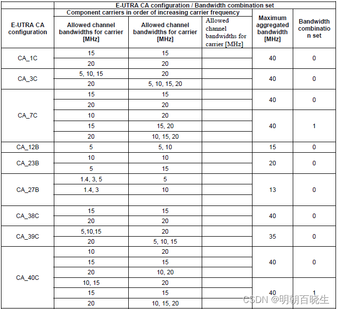
< 36.101 Table 5.6A.1-3: E-UTRA CA configurations and bandwidth combination sets defined for non-contiguous intra-band CA (with two sub-blocks) >< 36.101 Table 5.6A.1-3: E-UTRA CA configurations and bandwidth combination sets defined for non-contiguous intra-band CA (with two sub-blocks) >
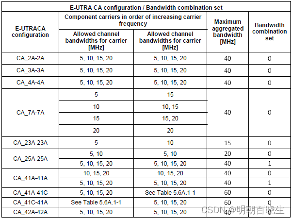
36.101 Table 5.6A.1-2: E-UTRA CA configurations and bandwidth combination sets defined for inter-band CA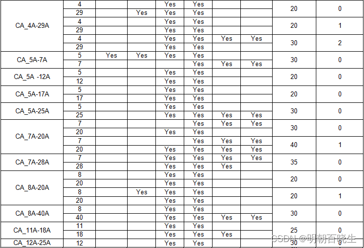
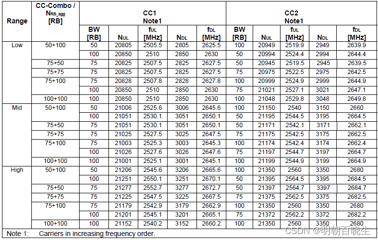
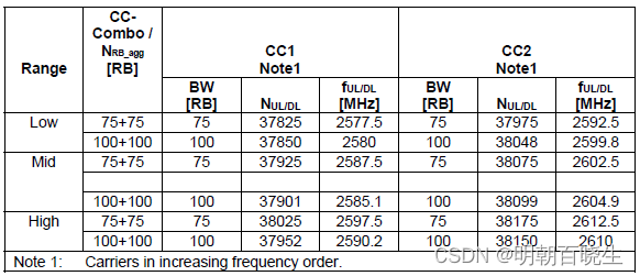
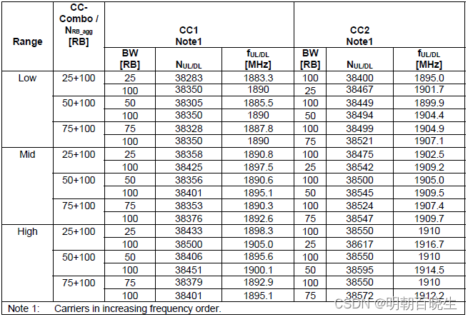
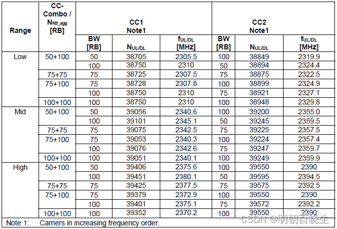
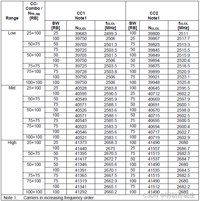
Test Frequency Tables >
For the specific test fequencies for each of the band combination, we need to refer to following tables in 36.508 (A lot of tables :)
- Table 4.3.1.1.1-1 : Test Frequencies for E-UTRA channel Bandwidth for operating band 1
- Table 4.3.1.1.1A-1 : Test Frequencies for CA_1C
- Table 4.3.1.1.2-1 : Test Frequencies for E-UTRA channel Bandwidth for operating band 2
- Table 4.3.1.1.3-1 : Test Frequencies for E-UTRA channel Bandwidth for operating band 3
- Table 4.3.1.1.3A-1 : Test Frequencies for CA_3C
- Table 4.3.1.1.4-1 : Test Frequencies for E-UTRA channel Bandwidth for operating band 4
- Table 4.3.1.1.5-1 : Test Frequencies for E-UTRA channel Bandwidth for operating band 5
- Table 4.3.1.1.6-1 : Test Frequencies for E-UTRA channel Bandwidth for operating band 6
- Table 4.3.1.1.7-1 : Test Frequencies for E-UTRA channel Bandwidth for operating band 7
- Table 4.3.1.1.7A-1 : Test Frequencies for CA_7C
- Table 4.3.1.1.8-1 : Test Frequencies for E-UTRA channel Bandwidth for operating band 8
- Table 4.3.1.1.9-1 : Test Frequencies for E-UTRA channel Bandwidth for operating band 9
- Table 4.3.1.1.10-1 : Test Frequencies for E-UTRA channel Bandwidth for operating band 10
- Table 4.3.1.1.11-1 : Test Frequencies for E-UTRA channel Bandwidth for operating band 11
- Table 4.3.1.1.12-1 : Test Frequencies for E-UTRA channel Bandwidth for operating band 12
- Table 4.3.1.1.13-1 : Test Frequencies for E-UTRA channel Bandwidth for operating band 13
- Table 4.3.1.1.14-1 : Test Frequencies for E-UTRA channel Bandwidth for operating band 14
- Table 4.3.1.1.17-1 : Test Frequencies for E-UTRA channel Bandwidth for operating band 17
- Table 4.3.1.1.18-1 : Test Frequencies for E-UTRA channel Bandwidth for operating band 18
- Table 4.3.1.1.19-1 : Test Frequencies for E-UTRA channel Bandwidth for operating band 19
- Table 4.3.1.1.20-1 : Test Frequencies for E-UTRA channel Bandwidth for operating band 20
- Table 4.3.1.1.21-1 : Test Frequencies for E-UTRA channel Bandwidth for operating band 21
- Table 4.3.1.1.22-1 : Test Frequencies for E-UTRA channel Bandwidth for operating band 22
- Table 4.3.1.1.23-1 : Test Frequencies for E-UTRA channel Bandwidth for operating band 23
- Table 4.3.1.1.24-1 : Test Frequencies for E-UTRA channel Bandwidth for operating band 24
- Table 4.3.1.1.25-1 : Test Frequencies for E-UTRA channel Bandwidth for operating band 25
- Table 4.3.1.1.26-1 : Test Frequencies for E-UTRA channel Bandwidth for operating band 26
- Table 4.3.1.1.27-1 : Test Frequencies for E-UTRA channel Bandwidth for operating band 27
- Table 4.3.1.1.27A-1 : Test Frequencies for CA_27B
- Table 4.3.1.1.28-1 : Test Frequencies for E-UTRA channel Bandwidth for operating band 28
- Table 4.3.1.1.29-1 : Test Frequencies for E-UTRA channel Bandwidth for operating band 29
- Table 4.3.1.1.31-1 : Test Frequencies for E-UTRA channel Bandwidth for operating band 31
- Table 4.3.1.2.1-1 : Test Frequencies for E-UTRA channel Bandwidth for operating band 33
- Table 4.3.1.2.2-1 : Test Frequencies for E-UTRA channel Bandwidth for operating band 34
- Table 4.3.1.2.3-1 : Test Frequencies for E-UTRA channel Bandwidth for operating band 35
- Table 4.3.1.2.4-1 : Test Frequencies for E-UTRA channel Bandwidth for operating band 36
- Table 4.3.1.2.5-1 : Test Frequencies for E-UTRA channel Bandwidth for operating band 37
- Table 4.3.1.2.6-1 : Test Frequencies for E-UTRA channel Bandwidth for operating band 38
- Table 4.3.1.2.6A-1 : Test Frequencies for CA_38C
- Table 4.3.1.2.7-1 : Test Frequencies for E-UTRA channel Bandwidth for operating band 39
- Table 4.3.1.2.7A-1 : Test Frequencies for CA_39C
- Table 4.3.1.2.8-1 : Test Frequencies for E-UTRA channel Bandwidth for operating band 40
- Table 4.3.1.2.8A-1 : Test Frequencies for CA_40C
- Table 4.3.1.2.9-1 : Test Frequencies for E-UTRA channel Bandwidth for operating band 41
- Table 4.3.1.2.9A-1 : Test Frequencies for CA_41C
- Table 4.3.1.2.10-1 : Test Frequencies for E-UTRA channel Bandwidth for operating band 42
- Table 4.3.1.2.11-1 : Test Frequencies for E-UTRA channel Bandwidth for operating band 43
- Table 4.3.1.2.12-1 : Test Frequencies for E-UTRA channel Bandwidth for operating band 44
- Table 4.3.1.2.13-1: Test frequencies for E-UTRA channel bandwidth for operating band 45
- Table 4.3.1.2.14A-1: Test frequencies for CA_46C
- Table 4.3.1.2.14A-2: Test frequencies for CA_46D
- Table 4.3.1.2.14A-3: Test frequencies for CA_46E
- Table 4.3.1.2.14A-4: Test frequencies for CA_46A-46A
- Table 4.3.1.2.15-1: Test frequencies for E-UTRA channel bandwidth for operating band 47
- Table 4.3.1.2.16-1: Test frequencies for E-UTRA channel bandwidth for operating band 48
One of the UE capability information that may confuses you would be following IE. This IE shows you which band are supported by the UE in terms of single carrier. It is not about Carrier Aggregation.
rf-Parameters
supportedBandListEUTRA: 4 items
Item 0
SupportedBandEUTRA
bandEUTRA: 2
..0. .... halfDuplex: False
Item 1
SupportedBandEUTRA
bandEUTRA: 4
.0.. .... halfDuplex: False
Item 2
SupportedBandEUTRA
bandEUTRA: 5
0... .... halfDuplex: False
Item 3
SupportedBandEUTRA
bandEUTRA: 17
.... ...0 halfDuplex: False
六 Determining Channel Spacing for Intra-band Contiguous CA
In case of Intraband Contiguous CA, figuring out channel spacing between two channels is not so easy because we need to put them togather without the guardband between each channel. The spacing between the two intraband contiguous CA channel can be calculated by following equation in 36.521-1 5.4.1A Channel spacing for CA
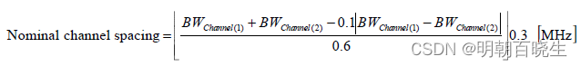
Based on this equation, I've calculated following cases.
| Channel 1 BW | Channel 2 BW | Channel Spacing |
| 20 | 20 | 19.8 |
| 20 | 15 | 17.1 |
| 20 | 10 | 14.4 |
| 20 | 5 | 11.7 |
| 15 | 15 | 15.0 |
| 15 | 10 | 12.0 |
| 15 | 5 | 9.3 |
| 10 | 10 | 9.9 |
| 10 | 5 | 7.2 |
| 5 | 5 | 4.8 |
You can check if my calculation is correct or not by referring to the test channel configuration specified in 36.508 as shown below.
七 How a Network know if a UE support Carrier Aggregation ?
The most important thing you have to pay attention in UE Capability Information is CA Band combination as specified in RRC message as shown below.
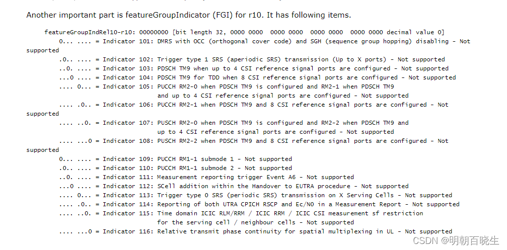
Another important part is featureGroupIndicator (FGI) for r10. It has following items.
八 Overall Sequence of Adding a Second Carrier
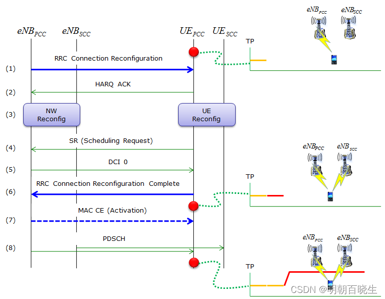
Following is an example for RRC Connection Reconfiguration for LTE advanced (Step 1). I just enabled all IE on ASN to give you full details of parameters, but it reality the implementation would start with very limited set of parameters enabled and leaving large portions of parameter to some 3GPP default or hardcoded configuration based on aggrement between UE maker and Network Operator.
First part you have to pay attention to this sample RRC message is sCellToAddModList-r10 which is for adding the SCC and next important thing is pucch-ConfigDedicated-v1020 which is for defining uplink control channel for reporting Ack/Nac for aggregated Carrier.
-rrcConnectionReconfiguration-r8 ::= SEQUENCE [000101]
+-measConfig ::= SEQUENCE OPTIONAL:Omit
+-mobilityControlInfo ::= SEQUENCE OPTIONAL:Omit
+-dedicatedInfoNASList ::= SEQUENCE OF OPTIONAL:Omit
+-radioResourceConfigDedicated ::= SEQUENCE [000101] OPTIONAL:Exist
| +-srb-ToAddModList ::= SEQUENCE OF OPTIONAL:Omit
| +-drb-ToAddModList ::= SEQUENCE OF OPTIONAL:Omit
| +-drb-ToReleaseList ::= SEQUENCE OF OPTIONAL:Omit
| +-mac-MainConfig ::= CHOICE [explicitValue] OPTIONAL:Exist
| | +-explicitValue ::= SEQUENCE [000]
| | +-ul-SCH-Config ::= SEQUENCE OPTIONAL:Omit
| | +-drx-Config ::= CHOICE OPTIONAL:Omit
| | +-timeAlignmentTimerDedicated ::= ENUMERATED [infinity]
| | +-phr-Config ::= CHOICE OPTIONAL:Omit
| | +-EXTENSION ::= SEQUENCE [01]
| | +-VERSION-BRACKETS1 ::= SEQUENCE OPTIONAL:Omit
| | +-VERSION-BRACKETS2 ::= SEQUENCE [1] OPTIONAL:Exist
| | +-mac-MainConfig-v1020 ::= SEQUENCE [111] OPTIONAL:Exist
| | +-sCellDeactivationTimer-r10 ::= ENUMERATED [rf16] OPTIONAL:Exist
| | +-extendedBSR-Sizes-r10 ::= ENUMERATED [setup] OPTIONAL:Exist
| | +-extendedPHR-r10 ::= ENUMERATED [setup] OPTIONAL:Exist
| +-sps-Config ::= SEQUENCE OPTIONAL:Omit
| +-physicalConfigDedicated ::= SEQUENCE [0000000000] OPTIONAL:Exist
| | +-pdsch-ConfigDedicated ::= SEQUENCE OPTIONAL:Omit
| | +-pucch-ConfigDedicated ::= SEQUENCE OPTIONAL:Omit
| | +-pusch-ConfigDedicated ::= SEQUENCE OPTIONAL:Omit
| | +-uplinkPowerControlDedicated ::= SEQUENCE OPTIONAL:Omit
| | +-tpc-PDCCH-ConfigPUCCH ::= CHOICE OPTIONAL:Omit
| | +-tpc-PDCCH-ConfigPUSCH ::= CHOICE OPTIONAL:Omit
| | +-cqi-ReportConfig ::= SEQUENCE OPTIONAL:Omit
| | +-soundingRS-UL-ConfigDedicated ::= CHOICE OPTIONAL:Omit
| | +-antennaInfo ::= CHOICE OPTIONAL:Omit
| | +-schedulingRequestConfig ::= CHOICE OPTIONAL:Omit
| | +-EXTENSION ::= SEQUENCE [010]
| | +-VERSION-BRACKETS1 ::= SEQUENCE OPTIONAL:Omit
| | +-VERSION-BRACKETS2 ::= SEQUENCE [00000111111] OPTIONAL:Exist
| | | +-antennaInfo-r10 ::= CHOICE OPTIONAL:Omit
| | | +-antennaInfoUL-r10 ::= SEQUENCE OPTIONAL:Omit
| | | +-cif-Presence-r10 ::= BOOLEAN OPTIONAL:Omit
| | | +-cqi-ReportConfig-r10 ::= SEQUENCE OPTIONAL:Omit
| | | +-csi-RS-Config-r10 ::= SEQUENCE OPTIONAL:Omit
| | | +-pucch-ConfigDedicated-v1020 ::= SEQUENCE [1111] OPTIONAL:Exist
| | | | +-pucch-Format-r10 ::= CHOICE [channelSelection-r10] OPTIONAL:Exist
| | | | | +-channelSelection-r10 ::= SEQUENCE [1]
| | | | | +-n1PUCCH-AN-CS-r10 ::= CHOICE [setup] OPTIONAL:Exist
| | | | | +-setup ::= SEQUENCE
| | | | | +-n1PUCCH-AN-CS-List-r10 ::= SEQUENCE OF SIZE(1..2) [2]
| | | | | +-N1PUCCH-AN-CS-r10 ::= SEQUENCE OF SIZE(1..4) [4]
| | | | | | +- ::= INTEGER (0..2047) [10]
| | | | | | +- ::= INTEGER (0..2047) [11]
| | | | | | +- ::= INTEGER (0..2047) [12]
| | | | | | +- ::= INTEGER (0..2047) [13]
| | | | | +-N1PUCCH-AN-CS-r10 ::= SEQUENCE OF SIZE(1..4) [4]
| | | | | +- ::= INTEGER (0..2047) [10]
| | | | | +- ::= INTEGER (0..2047) [11]
| | | | | +- ::= INTEGER (0..2047) [12]
| | | | | +- ::= INTEGER (0..2047) [13]
| | | | +-twoAntennaPortActivatedPUCCH-Format1a1b-r10 ::= ENUMERATED [true] OPTIONAL:Exist
| | | | +-simultaneousPUCCH-PUSCH-r10 ::= ENUMERATED [true] OPTIONAL:Exist
| | | | +-n1PUCCH-AN-RepP1-r10 ::= INTEGER (0..2047) [0] OPTIONAL:Exist
| | | +-pusch-ConfigDedicated-v1020 ::= SEQUENCE [000] OPTIONAL:Exist
| | | | +-betaOffsetMC-r10 ::= SEQUENCE OPTIONAL:Omit
| | | | +-groupHoppingDisabled-r10 ::= ENUMERATED OPTIONAL:Omit
| | | | +-dmrs-WithOCC-Activated-r10 ::= ENUMERATED OPTIONAL:Omit
| | | +-schedulingRequestConfig-v1020 ::= SEQUENCE [0] OPTIONAL:Exist
| | | | +-sr-PUCCH-ResourceIndexP1-r10 ::= INTEGER OPTIONAL:Omit
| | | +-soundingRS-UL-ConfigDedicated-v1020 ::= SEQUENCE OPTIONAL:Exist
| | | | +-srs-AntennaPort-r10 ::= ENUMERATED [an1]
| | | +-soundingRS-UL-ConfigDedicatedAperiodic-r10 ::= CHOICE [setup] OPTIONAL:Exist
| | | | +-setup ::= SEQUENCE [11]
| | | | +-srs-ConfigIndexAp-r10 ::= INTEGER (0..31) [0]
| | | | +-srs-ConfigApDCI-Format4-r10 ::= SEQUENCE OF SIZE(1..3) [1] OPTIONAL:Exist
| | | | | +-SRS-ConfigAp-r10 ::= SEQUENCE
| | | | | +-srs-AntennaPortAp-r10 ::= ENUMERATED [an1]
| | | | | +-srs-BandwidthAp-r10 ::= ENUMERATED [bw0]
| | | | | +-freqDomainPositionAp-r10 ::= INTEGER (0..23) [0]
| | | | | +-transmissionCombAp-r10 ::= INTEGER (0..1) [0]
| | | | | +-cyclicShiftAp-r10 ::= ENUMERATED [cs0]
| | | | +-srs-ActivateAp-r10 ::= CHOICE [release] OPTIONAL:Exist
| | | | +-release ::= NULL
| | | +-uplinkPowerControlDedicated-v1020 ::= SEQUENCE [11] OPTIONAL:Exist
| | | +-deltaTxD-OffsetListPUCCH-r10 ::= SEQUENCE OPTIONAL:Exist
| | | | +-deltaTxD-OffsetPUCCH-Format1-r10 ::= ENUMERATED [dB0]
| | | | +-deltaTxD-OffsetPUCCH-Format1a1b-r10 ::= ENUMERATED [dB0]
| | | | +-deltaTxD-OffsetPUCCH-Format22a2b-r10 ::= ENUMERATED [dB0]
| | | | +-deltaTxD-OffsetPUCCH-Format3-r10 ::= ENUMERATED [dB0]
| | | | +-EXTENSION ::= SEQUENCE
| | | +-pSRS-OffsetAp-r10 ::= INTEGER (0..15) [0] OPTIONAL:Exist
| | +-VERSION-BRACKETS3 ::= SEQUENCE OPTIONAL:Omit
| +-EXTENSION ::= SEQUENCE [00]
| +-VERSION-BRACKETS1 ::= SEQUENCE OPTIONAL:Omit
| +-VERSION-BRACKETS2 ::= SEQUENCE OPTIONAL:Omit
+-securityConfigHO ::= SEQUENCE OPTIONAL:Omit
+-nonCriticalExtension ::= SEQUENCE [01] OPTIONAL:Exist
+-lateNonCriticalExtension ::= OCTET STRING OPTIONAL:Omit
+-nonCriticalExtension ::= SEQUENCE [001] OPTIONAL:Exist
+-otherConfig-r9 ::= SEQUENCE OPTIONAL:Omit
+-fullConfig-r9 ::= ENUMERATED OPTIONAL:Omit
+-nonCriticalExtension ::= SEQUENCE [010] OPTIONAL:Exist
+-sCellToReleaseList-r10 ::= SEQUENCE OF OPTIONAL:Omit
+-sCellToAddModList-r10 ::= SEQUENCE OF SIZE(1..maxSCell-r10[4]) [1] OPTIONAL:Exist
| +-SCellToAddMod-r10 ::= SEQUENCE [111]
| +-sCellIndex-r10 ::= INTEGER (1..7) [1]
| +-cellIdentification-r10 ::= SEQUENCE OPTIONAL:Exist
| | +-physCellId-r10 ::= INTEGER (0..503) [2]
| | +-dl-CarrierFreq-r10 ::= INTEGER (0..maxEARFCN[65535]) [5790]
| +-radioResourceConfigCommonSCell-r10 ::= SEQUENCE [0] OPTIONAL:Exist
| | +-nonUL-Configuration-r10 ::= SEQUENCE [00]
| | | +-dl-Bandwidth-r10 ::= ENUMERATED [n50]
| | | +-antennaInfoCommon-r10 ::= SEQUENCE
| | | | +-antennaPortsCount ::= ENUMERATED [an2]
| | | +-mbsfn-SubframeConfigList-r10 ::= SEQUENCE OF OPTIONAL:Omit
| | | +-phich-Config-r10 ::= SEQUENCE
| | | | +-phich-Duration ::= ENUMERATED [normal]
| | | | +-phich-Resource ::= ENUMERATED [oneSixth]
| | | +-pdsch-ConfigCommon-r10 ::= SEQUENCE
| | | | +-referenceSignalPower ::= INTEGER (-60..50) [21]
| | | | +-p-b ::= INTEGER (0..3) [1]
| | | +-tdd-Config-r10 ::= SEQUENCE OPTIONAL:Omit
| | +-ul-Configuration-r10 ::= SEQUENCE OPTIONAL:Omit
| | +-EXTENSION ::= SEQUENCE
| +-radioResourceConfigDedicatedSCell-r10 ::= SEQUENCE [1] OPTIONAL:Exist
| | +-physicalConfigDedicatedSCell-r10 ::= SEQUENCE [11] OPTIONAL:Exist
| | | +-nonUL-Configuration-r10 ::= SEQUENCE [1111] OPTIONAL:Exist
| | | | +-antennaInfo-r10 ::= SEQUENCE [1] OPTIONAL:Exist
| | | | | +-transmissionMode-r10 ::= ENUMERATED [tm3]
| | | | | +-codebookSubsetRestriction-r10 ::= BIT STRING SIZE(ALIGNED) [00] OPTIONAL:Exist
| | | | | +-ue-TransmitAntennaSelection ::= CHOICE [release]
| | | | | +-release ::= NULL
| | | | +-crossCarrierSchedulingConfig-r10 ::= SEQUENCE OPTIONAL:Exist
| | | | | +-schedulingCellInfo-r10 ::= CHOICE [own-r10]
| | | | | +-own-r10 ::= SEQUENCE
| | | | | +-cif-Presence-r10 ::= BOOLEAN [FALSE]
| | | | +-csi-RS-Config-r10 ::= SEQUENCE [11] OPTIONAL:Exist
| | | | | +-csi-RS-r10 ::= CHOICE [setup] OPTIONAL:Exist
| | | | | | +-setup ::= SEQUENCE
| | | | | | +-antennaPortsCount-r10 ::= ENUMERATED [an1]
| | | | | | +-resourceConfig-r10 ::= INTEGER (0..31) [0]
| | | | | | +-subframeConfig-r10 ::= INTEGER (0..154) [0]
| | | | | | +-p-C-r10 ::= INTEGER (-8..15) [-8]
| | | | | +-zeroTxPowerCSI-RS-r10 ::= CHOICE [setup] OPTIONAL:Exist
| | | | | +-setup ::= SEQUENCE
| | | | | +-zeroTxPowerResourceConfigList-r10 ::= BIT STRING SIZE(16) [0000000000000000]
| | | | | +-zeroTxPowerSubframeConfig-r10 ::= INTEGER (0..154) [0]
| | | | +-pdsch-ConfigDedicated-r10 ::= SEQUENCE OPTIONAL:Exist
| | | | +-p-a ::= ENUMERATED [dB-3]
| | | +-ul-Configuration-r10 ::= SEQUENCE [1111111] OPTIONAL:Exist
| | | | +-antennaInfoUL-r10 ::= SEQUENCE [11] OPTIONAL:Exist
| | | | | +-transmissionModeUL-r10 ::= ENUMERATED [tm1] OPTIONAL:Exist
| | | | | +-fourAntennaPortActivated-r10 ::= ENUMERATED [setup] OPTIONAL:Exist
| | | | +-pusch-ConfigDedicatedSCell-r10 ::= SEQUENCE [11] OPTIONAL:Exist
| | | | | +-groupHoppingDisabled-r10 ::= ENUMERATED [true] OPTIONAL:Exist
| | | | | +-dmrs-WithOCC-Activated-r10 ::= ENUMERATED [true] OPTIONAL:Exist
| | | | +-uplinkPowerControlDedicatedSCell-r10 ::= SEQUENCE [11] OPTIONAL:Exist
| | | | | +-p0-UE-PUSCH-r10 ::= INTEGER (-8..7) [-8]
| | | | | +-deltaMCS-Enabled-r10 ::= ENUMERATED [en0]
| | | | | +-accumulationEnabled-r10 ::= BOOLEAN [FALSE]
| | | | | +-pSRS-Offset-r10 ::= INTEGER (0..15) [0]
| | | | | +-pSRS-OffsetAp-r10 ::= INTEGER (0..15) [0] OPTIONAL:Exist
| | | | | +-filterCoefficient-r10 ::= ENUMERATED [fc0] OPTIONAL:Exist
| | | | | +-pathlossReferenceLinking-r10 ::= ENUMERATED [pCell]
| | | | +-cqi-ReportConfigSCell-r10 ::= SEQUENCE [111] OPTIONAL:Exist
| | | | | +-cqi-ReportModeAperiodic-r10 ::= ENUMERATED [rm12] OPTIONAL:Exist
| | | | | +-nomPDSCH-RS-EPRE-Offset-r10 ::= INTEGER (-1..6) [-1]
| | | | | +-cqi-ReportPeriodicSCell-r10 ::= CHOICE [setup] OPTIONAL:Exist
| | | | | | +-setup ::= SEQUENCE [0000]
| | | | | | +-cqi-PUCCH-ResourceIndex-r10 ::= INTEGER (0..1184) [0]
| | | | | | +-cqi-PUCCH-ResourceIndexP1-r10 ::= INTEGER OPTIONAL:Omit
| | | | | | +-cqi-pmi-ConfigIndex ::= INTEGER (0..1023) [0]
| | | | | | +-cqi-FormatIndicatorPeriodic-r10 ::= CHOICE [widebandCQI-r10]
| | | | | | | +-widebandCQI-r10 ::= SEQUENCE [0]
| | | | | | | +-csi-ReportMode-r10 ::= ENUMERATED OPTIONAL:Omit
| | | | | | +-ri-ConfigIndex ::= INTEGER OPTIONAL:Omit
| | | | | | +-simultaneousAckNackAndCQI ::= BOOLEAN [FALSE]
| | | | | | +-cqi-Mask-r9 ::= ENUMERATED OPTIONAL:Omit
| | | | | | +-csi-ConfigIndex-r10 ::= CHOICE OPTIONAL:Omit
| | | | | +-pmi-RI-Report-r10 ::= ENUMERATED [setup] OPTIONAL:Exist
| | | | +-soundingRS-UL-ConfigDedicated-r10 ::= CHOICE [setup] OPTIONAL:Exist
| | | | | +-setup ::= SEQUENCE
| | | | | +-srs-Bandwidth ::= ENUMERATED [bw0]
| | | | | +-srs-HoppingBandwidth ::= ENUMERATED [hbw0]
| | | | | +-freqDomainPosition ::= INTEGER (0..23) [0]
| | | | | +-duration ::= BOOLEAN [FALSE]
| | | | | +-srs-ConfigIndex ::= INTEGER (0..1023) [0]
| | | | | +-transmissionComb ::= INTEGER (0..1) [0]
| | | | | +-cyclicShift ::= ENUMERATED [cs0]
| | | | +-soundingRS-UL-ConfigDedicated-v1020 ::= SEQUENCE OPTIONAL:Exist
| | | | | +-srs-AntennaPort-r10 ::= ENUMERATED [an1]
| | | | +-soundingRS-UL-ConfigDedicatedAperiodic-r10 ::= CHOICE [setup] OPTIONAL:Exist
| | | | +-setup ::= SEQUENCE [11]
| | | | +-srs-ConfigIndexAp-r10 ::= INTEGER (0..31) [0]
| | | | +-srs-ConfigApDCI-Format4-r10 ::= SEQUENCE OF SIZE(1..3) [1] OPTIONAL:Exist
| | | | | +-SRS-ConfigAp-r10 ::= SEQUENCE
| | | | | +-srs-AntennaPortAp-r10 ::= ENUMERATED [an1]
| | | | | +-srs-BandwidthAp-r10 ::= ENUMERATED [bw0]
| | | | | +-freqDomainPositionAp-r10 ::= INTEGER (0..23) [0]
| | | | | +-transmissionCombAp-r10 ::= INTEGER (0..1) [0]
| | | | | +-cyclicShiftAp-r10 ::= ENUMERATED [cs0]
| | | | +-srs-ActivateAp-r10 ::= CHOICE [release] OPTIONAL:Exist
| | | | +-release ::= NULL
| | | +-EXTENSION ::= SEQUENCE
| | +-EXTENSION ::= SEQUENCE
| +-EXTENSION ::= SEQUENCE
九 Evolution path of Carrier Aggregation / Possible Test Plan
It's already been over an year since the first LTE-A was deployed since July 2013 in Korea and now it is getting spreaded wider. I tried to list up possible evolution path of LTE-A development in terms of chipset development aspect and UE development. This can be a big picture of test plan. I would be good practice if you think on your own about why we need these test and what kind of challenge UE (or chipset) should overcome to pass each of these test. You don't have to get the answers to your question.. just think about it as much as possible and it would let you think about a lot of details.
- 2 CC Aggregation - SISO, Cat 3, PUSCH enabled : HARQ Ack/Nack is carried by PUSCH
- 2 CC Aggregation - SISO, Cat 3, PUSCH diabled : HARQ Ack/Nack is carried by PUCCH Format 1b
- 2 CC Aggregation - SISO with CSI Report - Periodic
- 2 CC Aggregation - SISO with CSI Report - Aperiodic
- 2 CC Aggregation - SISO, Handover for SCC Change
- 2 CC Aggregation - SISO, Handover for PCC Change
- 2 CC Aggregation - SISO, Handover for both SCC and PCC Change
- 2 CC Aggregation - 2x2 MIMO, Cat 3, PUSCH enabled : HARQ Ack/Nack is carried by PUSCH
- 2 CC Aggregation - 2x2 MIMO, Cat 3, PUSCH diabled : HARQ Ack/Nack is carried by PUCCH Format 1b
- 2 CC Aggregation - 2x2 MIMO, Cat 3, 40 Mhz Aggregated BandWidth, 200 Mbps Throughput at IP layer
- 2 CC Aggregation - SISO, Cat 4, PUSCH enabled : HARQ Ack/Nack is carried by PUSCH
- 2 CC Aggregation - SISO, Cat 4, PUSCH diabled : HARQ Ack/Nack is carried by PUCCH Format 1b
- 2 CC Aggregation - 2x2 MIMO, Cat 6, MIMO, 20 Mhz Aggregated Bandwidth, 150 Mbps Throughput at IP layer
- 2 CC Aggregation - 2x2 MIMO, Cat 6, MIMO, 40 Mhz Aggregated Bandwidth, 300 Mbps Throughput at IP layer
- 2 CC Aggregation - TM 8
- 2 CC Aggregation - TM 9
- 3 CC Aggregation - SISO, Cat 6, 30 Mhz Aggregated BW, PUSCH enabled : HARQ Ack/Nack is carried by PUSCH
- 3 CC Aggregation - SISO, Cat 6, 30 Mhz Aggregated BW,PUSCH diabled : HARQ Ack/Nack is carried by PUCCH Format 3
- 3 CC Aggregation - 2x2 MIMO, Cat 6, 30 Mhz Aggregated BW, PUSCH enabled : HARQ Ack/Nack is carried by PUSCH
- 3 CC Aggregation - 2x2 MIMO, Cat 6, 30 Mhz Aggregated BW, PUSCH diabled : HARQ Ack/Nack is carried by PUCCH Format 3
- 3 CC Aggregation - 2x2 MIMO, Cat 6, 40 Mhz Aggregated BW
- 3 CC Aggregation - 2x2 MIMO, Cat 6, 60 Mhz Aggregated BW
- 3 CC Aggregation - 4x4,4x4,4x2 Cat 16, 60 Mhz Aggregated BW
- 4 CC Aggregation - All 2x2, 80 Mhz Aggregated BW
- 5 CC Aggregation - All 2x2, 100 Mhz Aggregated BW
- 5 CC Aggregation - All 4x4, 100 Mhz Aggregated BW
这篇关于[移动通讯]【Carrier Aggregation-10】【 Radio Resource Control (RRC) Aspects】的文章就介绍到这儿,希望我们推荐的文章对编程师们有所帮助!


