本文主要是介绍GRE_MGRE综合实验,希望对大家解决编程问题提供一定的参考价值,需要的开发者们随着小编来一起学习吧!
目录
1、R5为ISP,只能进行IP地址配置,其所有地址均配为公有IP地址。
IP配置
配置公网全网通
2、(1)R1和R5间使用PPP的PAP认证,R5为主认证方。
PAP认证
(2)R2与R5之间使用ppp的CHAP认证,R5为主认证方。
(3)R3与R5之间使用HDLC封装。
3、R1、R2、R3构建一个MGRE环境,R1为中心站点,R1、R4间为点到点的GRE。
构建隧道
配置NHRP
查看
配置GRE隧道
4、整个私有网络基于RIP全网可达。
RIP配置
开启R1Tunnel0/0/0口的伪广播功能
关闭水平分割
5、所有PC设置私有IP为源IP,可以访问R5环回,实现全网通。
easy IP配置

1、R5为ISP,只能进行IP地址配置,其所有地址均配为公有IP地址。
IP配置
R1:
<Huawei>sys
Enter system view, return user view with Ctrl+Z.
[Huawei]sysname R1
[R1]int g0/0/0
[R1-GigabitEthernet0/0/0]ip add 192.168.1.1 24
Mar 29 2024 16:47:26-08:00 R1 %%01IFNET/4/LINK_STATE(l)[0]:The line protocol IP
on the interface GigabitEthernet0/0/0 has entered the UP state.
[R1-GigabitEthernet0/0/0]q
[R1]int s4/0/0
[R1-Serial4/0/0]ip add 15.1.1.1 24
[R1-Serial4/0/0]q
[R1]dis ip int b
*down: administratively down
^down: standby
(l): loopback
(s): spoofing
The number of interface that is UP in Physical is 3
The number of interface that is DOWN in Physical is 3
The number of interface that is UP in Protocol is 3
The number of interface that is DOWN in Protocol is 3Interface                         IP Address/Mask      Physical   Protocol
GigabitEthernet0/0/0              192.168.1.1/24       up         up
GigabitEthernet0/0/1              unassigned           down       down
GigabitEthernet0/0/2              unassigned           down       down
NULL0                             unassigned           up         up(s)
Serial4/0/0                       15.1.1.1/24          up         up
Serial4/0/1                       unassigned           down       down
[R1]
R2:
<Huawei>sys
Enter system view, return user view with Ctrl+Z.
[Huawei]sysname R2
[R2]int g0/0/0
[R2-GigabitEthernet0/0/0]ip add 192.168.2.2 24
Mar 29 2024 16:49:49-08:00 R2 %%01IFNET/4/LINK_STATE(l)[0]:The line protocol IP
on the interface GigabitEthernet0/0/0 has entered the UP state.
[R2-GigabitEthernet0/0/0]q
[R2]int s4/0/0
[R2-Serial4/0/0]ip add 25.1.1.2 24
[R2-Serial4/0/0]q
[R2]dis ip int b
*down: administratively down
^down: standby
(l): loopback
(s): spoofing
The number of interface that is UP in Physical is 3
The number of interface that is DOWN in Physical is 3
The number of interface that is UP in Protocol is 3
The number of interface that is DOWN in Protocol is 3Interface                         IP Address/Mask      Physical   Protocol
GigabitEthernet0/0/0              192.168.2.2/24       up         up
GigabitEthernet0/0/1              unassigned           down       down
GigabitEthernet0/0/2              unassigned           down       down
NULL0                             unassigned           up         up(s)
Serial4/0/0                       25.1.1.2/24          up         up
Serial4/0/1                       unassigned           down       down
[R2]
R3:
<Huawei>sys
Enter system view, return user view with Ctrl+Z.
[Huawei]sysname R3
[R3]int g0/0/0
[R3-GigabitEthernet0/0/0]ip add 192.168.3.3 24
[R3-GigabitEthernet0/0/0]
Mar 29 2024 16:52:19-08:00 R3 %%01IFNET/4/LINK_STATE(l)[0]:The line protocol IP
on the interface GigabitEthernet0/0/0 has entered the UP state.
[R3-GigabitEthernet0/0/0]q
[R3]int s4/0/0
[R3-Serial4/0/0]ip add 35.1.1.3 24
[R3-Serial4/0/0]q
[R3]dis ip int b
*down: administratively down
^down: standby
(l): loopback
(s): spoofing
The number of interface that is UP in Physical is 3
The number of interface that is DOWN in Physical is 3
The number of interface that is UP in Protocol is 3
The number of interface that is DOWN in Protocol is 3Interface                         IP Address/Mask      Physical   Protocol
GigabitEthernet0/0/0              192.168.3.3/24       up         up
GigabitEthernet0/0/1              unassigned           down       down
GigabitEthernet0/0/2              unassigned           down       down
NULL0                             unassigned           up         up(s)
Serial4/0/0                       35.1.1.3/24          up         up
Serial4/0/1                       unassigned           down       down
[R3]
R4:
<Huawei>sys
Enter system view, return user view with Ctrl+Z.
[Huawei]sysname R4
[R4]int g0/0/0
[R4-GigabitEthernet0/0/0]ip add 45.1.1.4 24
Mar 29 2024 16:54:35-08:00 R4 %%01IFNET/4/LINK_STATE(l)[0]:The line protocol IP
on the interface GigabitEthernet0/0/0 has entered the UP state.
[R4-GigabitEthernet0/0/0]q
[R4]int g0/0/1
[R4-GigabitEthernet0/0/1]ip add 192.168.4.4 24
Mar 29 2024 16:54:52-08:00 R4 %%01IFNET/4/LINK_STATE(l)[1]:The line protocol IP
on the interface GigabitEthernet0/0/1 has entered the UP state.
[R4-GigabitEthernet0/0/1]q
[R4]dis ip int b
*down: administratively down
^down: standby
(l): loopback
(s): spoofing
The number of interface that is UP in Physical is 3
The number of interface that is DOWN in Physical is 1
The number of interface that is UP in Protocol is 3
The number of interface that is DOWN in Protocol is 1Interface                         IP Address/Mask      Physical   Protocol
GigabitEthernet0/0/0              45.1.1.4/24          up         up
GigabitEthernet0/0/1              192.168.4.4/24       up         up
GigabitEthernet0/0/2              unassigned           down       down
NULL0                             unassigned           up         up(s)
[R4]
ISP:
<Huawei>sys
Enter system view, return user view with Ctrl+Z.
[Huawei]sysname ISP
[ISP]int s4/0/1
[ISP-Serial4/0/1]ip add 15.1.1.5 24
[ISP-Serial4/0/1]
Mar 29 2024 16:56:20-08:00 ISP %%01IFNET/4/LINK_STATE(l)[0]:The line protocol PP
P IPCP on the interface Serial4/0/1 has entered the UP state.
[ISP-Serial4/0/1]q
[ISP]int s3/0/1
[ISP-Serial3/0/1]ip add 25.1.1.5 24
[ISP-Serial3/0/1]
Mar 29 2024 16:56:43-08:00 ISP %%01IFNET/4/LINK_STATE(l)[1]:The line protocol PP
P IPCP on the interface Serial3/0/1 has entered the UP state.
[ISP-Serial3/0/1]q
[ISP]int s4/0/0
[ISP-Serial4/0/0]ip add 35.1.1.5 24
[ISP-Serial4/0/0]
Mar 29 2024 16:57:01-08:00 ISP %%01IFNET/4/LINK_STATE(l)[2]:The line protocol PP
P IPCP on the interface Serial4/0/0 has entered the UP state.
[ISP-Serial4/0/0]q
[ISP]int g0/0/0
[ISP-GigabitEthernet0/0/0]ip add 45.1.1.5 24
Mar 29 2024 16:57:47-08:00 ISP %%01IFNET/4/LINK_STATE(l)[3]:The line protocol IPon the interface GigabitEthernet0/0/0 has entered the UP state.
[ISP-GigabitEthernet0/0/0]q
[ISP]int LoopBack 0
[ISP-LoopBack0]ip add 5.5.5.5 24
[ISP-LoopBack0]q
[ISP]dis ip int b
*down: administratively down
^down: standby
(l): loopback
(s): spoofing
The number of interface that is UP in Physical is 6
The number of interface that is DOWN in Physical is 3
The number of interface that is UP in Protocol is 6
The number of interface that is DOWN in Protocol is 3Interface                         IP Address/Mask      Physical   Protocol
GigabitEthernet0/0/0              45.1.1.5/24          up         up
GigabitEthernet0/0/1              unassigned           down       down
GigabitEthernet0/0/2              unassigned           down       down
LoopBack0                         5.5.5.5/24           up         up(s)
NULL0                             unassigned           up         up(s)
Serial3/0/0                       unassigned           down       down
Serial3/0/1                       25.1.1.5/24          up         up
Serial4/0/0                       35.1.1.5/24          up         up
Serial4/0/1                       15.1.1.5/24          up         up
[ISP]
PC1:

PC2:

PC3:

PC4:

配置公网全网通
R1:
[R1]ip route-static 0.0.0.0 0 15.1.1.5R2:
[R2]ip route-static 0.0.0.0 0 25.1.1.5R3:
[R3]ip route-static 0.0.0.0 0 35.1.1.5R4:
[R4]ip route-static 0.0.0.0 0 45.1.1.5
2、(1)R1和R5间使用PPP的PAP认证,R5为主认证方。
PAP认证
ISP为主认证方,所以在ISP上配置账户:
R5:
[ISP]aaa
[ISP-aaa]local-user a1 password cipher a12345
Info: Add a new user.
[ISP-aaa]local-user a1 service-type ppp
[ISP-aaa]q
[ISP]int s4/0/1
[ISP-Serial4/0/1]ppp authentication-mode pap
R1:
[R1]int s4/0/0
[R1-Serial4/0/0]ppp pap local-user a1 password cipher a12345
验证:
[R1-Serial4/0/0]shutdown
Mar 29 2024 18:12:22-08:00 R1 %%01PPP/4/PHYSICALDOWN(l)[0]:On the interface Seri
al4/0/0, PPP link was closed because the status of the physical layer was Down. [R1-Serial4/0/0]
Mar 29 2024 18:12:22-08:00 R1 %%01IFNET/4/LINK_STATE(l)[1]:The line protocol PPPon the interface Serial4/0/0 has entered the DOWN state.
[R1-Serial4/0/0]
Mar 29 2024 18:12:22-08:00 R1 %%01IFNET/4/LINK_STATE(l)[2]:The line protocol PPPIPCP on the interface Serial4/0/0 has entered the DOWN state.
[R1-Serial4/0/0]
Mar 29 2024 18:12:22-08:00 R1 %%01IFPDT/4/IF_STATE(l)[3]:Interface Serial4/0/0 h
as turned into DOWN state.
[R1-Serial4/0/0]undo shutdown
[R1-Serial4/0/0]
Mar 29 2024 18:12:31-08:00 R1 %%01IFPDT/4/IF_STATE(l)[4]:Interface Serial4/0/0 h
as turned into UP state.
[R1-Serial4/0/0]
Mar 29 2024 18:12:34-08:00 R1 %%01IFNET/4/LINK_STATE(l)[5]:The line protocol PPPon the interface Serial4/0/0 has entered the UP state.
[R1-Serial4/0/0]
Mar 29 2024 18:12:34-08:00 R1 %%01IFNET/4/LINK_STATE(l)[6]:The line protocol PPPIPCP on the interface Serial4/0/0 has entered the UP state.
[R1-Serial4/0/0]
(2)R2与R5之间使用ppp的CHAP认证,R5为主认证方。
依然是R5为主,故在R5上配置账户:
R5:
[ISP]aaa
[ISP-aaa]local-user b1 password cipher b12345
Info: Add a new user.
[ISP-aaa]local-user b1 service-type ppp
[ISP-aaa]q
[ISP-Serial3/0/1]ppp authentication-mode chap
R2:
[R2]int s4/0/0
[R2-Serial4/0/0]ppp chap user b1
[R2-Serial4/0/0]ppp chap password cipher b12345
验证:
[R2-Serial4/0/0]shutdown
Mar 29 2024 18:17:41-08:00 R2 %%01PPP/4/PHYSICALDOWN(l)[0]:On the interface Seri
al4/0/0, PPP link was closed because the status of the physical layer was Down. [R2-Serial4/0/0]
Mar 29 2024 18:17:41-08:00 R2 %%01IFNET/4/LINK_STATE(l)[1]:The line protocol PPPon the interface Serial4/0/0 has entered the DOWN state.
[R2-Serial4/0/0]
Mar 29 2024 18:17:41-08:00 R2 %%01IFNET/4/LINK_STATE(l)[2]:The line protocol PPPIPCP on the interface Serial4/0/0 has entered the DOWN state.
[R2-Serial4/0/0]
Mar 29 2024 18:17:41-08:00 R2 %%01IFPDT/4/IF_STATE(l)[3]:Interface Serial4/0/0 h
as turned into DOWN state.
[R2-Serial4/0/0]undo shutdown
[R2-Serial4/0/0]
Mar 29 2024 18:17:50-08:00 R2 %%01IFPDT/4/IF_STATE(l)[4]:Interface Serial4/0/0 h
as turned into UP state.
[R2-Serial4/0/0]
Mar 29 2024 18:17:53-08:00 R2 %%01IFNET/4/LINK_STATE(l)[5]:The line protocol PPPon the interface Serial4/0/0 has entered the UP state.
[R2-Serial4/0/0]
Mar 29 2024 18:17:54-08:00 R2 %%01IFNET/4/LINK_STATE(l)[6]:The line protocol PPPIPCP on the interface Serial4/0/0 has entered the UP state.
[R2-Serial4/0/0]
(3)R3与R5之间使用HDLC封装。
R5:
[ISP]int s4/0/0
[ISP-Serial4/0/0]link-protocol hdlc
Warning: The encapsulation protocol of the link will be changed. Continue? [Y/N]
:y
Mar 29 2024 18:22:40-08:00 ISP %%01IFNET/4/CHANGE_ENCAP(l)[14]:The user performe
d the configuration that will change the encapsulation protocol of the link and
then selected Y.
[ISP-Serial4/0/0]
[ISP-Serial4/0/0]
Mar 29 2024 18:22:40-08:00 ISP %%01PPP/4/PHYSICALDOWN(l)[15]:On the interface Se
rial4/0/0, PPP link was closed because the status of the physical layer was Down
.
[ISP-Serial4/0/0]
Mar 29 2024 18:22:40-08:00 ISP %%01IFNET/4/LINK_STATE(l)[16]:The line protocol P
PP on the interface Serial4/0/0 has entered the DOWN state.
[ISP-Serial4/0/0]
Mar 29 2024 18:22:40-08:00 ISP %%01IFNET/4/LINK_STATE(l)[17]:The line protocol P
PP IPCP on the interface Serial4/0/0 has entered the DOWN state.
[ISP-Serial4/0/0]
Mar 29 2024 18:22:40-08:00 ISP %%01IFPDT/4/IF_STATE(l)[18]:Interface Serial4/0/0has turned into DOWN state.
[ISP-Serial4/0/0]
Mar 29 2024 18:22:41-08:00 ISP %%01IFPDT/4/IF_STATE(l)[19]:Interface Serial4/0/0has turned into UP state.
[ISP-Serial4/0/0]
Mar 29 2024 18:22:41-08:00 ISP %%01IFNET/4/LINK_STATE(l)[20]:The line protocol I
P on the interface Serial4/0/0 has entered the UP state.
[ISP-Serial4/0/0]
R3:
[R3]int s4/0/0
[R3-Serial4/0/0]link-protocol hdlc
Warning: The encapsulation protocol of the link will be changed. Continue? [Y/N]
:y
Mar 29 2024 18:23:02-08:00 R3 %%01IFNET/4/CHANGE_ENCAP(l)[0]:The user performed
the configuration that will change the encapsulation protocol of the link and th
en selected Y.
[R3-Serial4/0/0]
Mar 29 2024 18:23:02-08:00 R3 %%01PPP/4/PHYSICALDOWN(l)[1]:On the interface Seri
al4/0/0, PPP link was closed because the status of the physical layer was Down. [R3-Serial4/0/0]
Mar 29 2024 18:23:02-08:00 R3 %%01IFNET/4/LINK_STATE(l)[2]:The line protocol PPPon the interface Serial4/0/0 has entered the DOWN state.
[R3-Serial4/0/0]
Mar 29 2024 18:23:02-08:00 R3 %%01IFNET/4/LINK_STATE(l)[3]:The line protocol PPPIPCP on the interface Serial4/0/0 has entered the DOWN state.
[R3-Serial4/0/0]
Mar 29 2024 18:23:02-08:00 R3 %%01IFPDT/4/IF_STATE(l)[4]:Interface Serial4/0/0 h
as turned into DOWN state.
[R3-Serial4/0/0]
Mar 29 2024 18:23:03-08:00 R3 %%01IFPDT/4/IF_STATE(l)[5]:Interface Serial4/0/0 h
as turned into UP state.
[R3-Serial4/0/0]
Mar 29 2024 18:23:03-08:00 R3 %%01IFNET/4/LINK_STATE(l)[6]:The line protocol IP
on the interface Serial4/0/0 has entered the UP state.
[R3-Serial4/0/0]
验证:


3、R1、R2、R3构建一个MGRE环境,R1为中心站点,R1、R4间为点到点的GRE。
构建隧道
首先配置MGRE隧道:
R1:
[R1]int Tunnel 0/0/0
[R1-Tunnel0/0/0]ip add 10.1.2.1 24
[R1-Tunnel0/0/0]tunnel-protocol gre p2mp
[R1-Tunnel0/0/0]source 15.1.1.1
Mar 29 2024 18:33:05-08:00 R1 %%01IFNET/4/LINK_STATE(l)[0]:The line protocol IP
on the interface Tunnel0/0/0 has entered the UP state.
[R1-Tunnel0/0/0]
R2:
[R2]int Tunnel 0/0/0
[R2-Tunnel0/0/0]ip add 10.1.2.2 24
[R2-Tunnel0/0/0]tunnel-protocol gre p2mp
[R2-Tunnel0/0/0]source s4/0/0
Mar 29 2024 18:35:02-08:00 R2 %%01IFNET/4/LINK_STATE(l)[0]:The line protocol IP
on the interface Tunnel0/0/0 has entered the UP state.
R3:
[R3]int Tunnel 0/0/0
[R3-Tunnel0/0/0]ip add 10.1.2.3 24
[R3-Tunnel0/0/0]tunnel-protocol gre p2mp
[R3-Tunnel0/0/0]source s4/0/0
Mar 29 2024 18:36:12-08:00 R3 %%01IFNET/4/LINK_STATE(l)[0]:The line protocol IP
on the interface Tunnel0/0/0 has entered the UP state.
[R3-Tunnel0/0/0]
配置NHRP
R1:
[R1-Tunnel0/0/0]nhrp network-id 100R2:
[R2-Tunnel0/0/0]nhrp network-id 100
[R2-Tunnel0/0/0]nhrp entry 10.1.2.1 15.1.1.1 register
R3:
[R3-Tunnel0/0/0]nhrp network-id 100
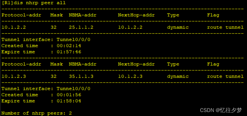
[R3-Tunnel0/0/0]nhrp entry 10.1.2.1 15.1.1.1 register 查看
配置GRE隧道
R1:
[R1]int Tunnel 0/0/1
[R1-Tunnel0/0/1]ip add 10.1.1.1 24
[R1-Tunnel0/0/1]tunnel-protocol gre
[R1-Tunnel0/0/1]source 15.1.1.1
[R1-Tunnel0/0/1]destination 45.1.1.4
R4:
[R4]int Tunnel 0/0/1
[R4-Tunnel0/0/1]ip add 10.1.1.2 24
[R4-Tunnel0/0/1]tunnel-protocol gre
[R4-Tunnel0/0/1]source 45.1.1.4
[R4-Tunnel0/0/1]destination 15.1.1.1
R1:

R4:

4、整个私有网络基于RIP全网可达。
RIP配置
R1:
[R1]rip 1
[R1-rip-1]version 2
[R1-rip-1]undo summary
[R1-rip-1]network 192.168.1.0
[R1-rip-1]network 10.0.0.0
[R1-rip-1]
R2:
[R2]rip 1
[R2-rip-1]v 2
[R2-rip-1]undo summary
[R2-rip-1]network 192.168.2.0
[R2-rip-1]network 10.0.0.0
R3:
[R3]rip 1
[R3-rip-1]version 2
[R3-rip-1]undo summary
[R3-rip-1]network 192.168.3.0
[R3-rip-1]network 10.0.0.0
R4:
[R4]rip 1
[R4-rip-1]v 2
[R4-rip-1]undo summary
[R4-rip-1]network 192.168.4.0
[R4-rip-1]network 10.0.0.0
开启R1Tunnel0/0/0口的伪广播功能
[R1-Tunnel0/0/0]nhrp entry multicast dynamic 关闭水平分割
水平分割 --- 从哪个接口学到的路由信息将不再从这个接口发出去。
故使用rip的路由器不能发送其他主机的路由信息,要实现全网通,我们就得关闭该功能。
R1:
[R1-Tunnel0/0/0]undo rip split-horizon R2:
[R2-Tunnel0/0/0]undo rip split-horizon R3:
[R3-Tunnel0/0/0]undo rip split-horizon 至此,R2和R3就能学习到其他的路由信息。
R2 ping 一下R3后再查看 NHRP表(因为两台路由器间没有发包可能不会更新NHRP表):
R2:

R3:

5、所有PC设置私有IP为源IP,可以访问R5环回,实现全网通。
easy IP配置
R1:
[R1]acl 2000
[R1-acl-basic-2000]rule permit source 192.168.1.0 0.0.0.255
[R1-acl-basic-2000]q
[R1]int s4/0/0
[R1-Serial4/0/0]nat outbound 2000
检验:

R2:
[R2]acl 2000
[R2-acl-basic-2000]rule permit source 192.168.2.0 0.0.0.255
[R2-acl-basic-2000]q
[R2]int s4/0/0
[R2-Serial4/0/0]nat outbound 2000
检验:

R3:
[R3]acl 2000
[R3-acl-basic-2000]rule permit source 192.168.3.0 0.0.0.255
[R3-acl-basic-2000]q
[R3]int s4/0/0
[R3-Serial4/0/0]nat outbound 2000
检验:

R4:
[R4]acl 2000
[R4-acl-basic-2000]rule permit source 192.168.4.0 0.0.0.255
[R4-acl-basic-2000]q
[R4]int g0/0/0
[R4-GigabitEthernet0/0/0]nat outbound 2000
检验:

这篇关于GRE_MGRE综合实验的文章就介绍到这儿,希望我们推荐的文章对编程师们有所帮助!