本文主要是介绍【ESP-C3-32S-Kit 2M开发板环境搭建Arduino】,希望对大家解决编程问题提供一定的参考价值,需要的开发者们随着小编来一起学习吧!
目录
前言
相关安装包资料获取
一、下载安装ArduinoIDE
1.开始安装Arduino
2.选择安装的文件
3. 选择安装路径
4. 安装完成
二、ArduinoIDE的ESP32C2目录导入
1. 点击Arduino文件选项,选择首选项
2. 添加开发板地址
3. 替换原来的文件Arduino15
三、运行开发板示例并展示效果
1. 选择一个AnalogOut的LEDSoftwareFade
2. 选择好对应的开发板型号
3. 点击✔按钮进行编译
4. 点击➡按钮进行代码上传
5. 实际运行的效果图
四. 小结
模块采用优信电子的ESP-C3-32S-Kit 2M开发板

前言
近期学习ESP32C3 Arduino开发,在搭建Arduino IDE的 安信可 ESP32C3系列模组的开发环境时遇到问题,安照Arduino IDE的指引设置,网速不行,下载失败!
相信大家也遇到过网速不行,下载失败的情况,下面我来教教大家如何使用本地的网络快速的搭建Arduino开发环境,具体步骤如下
相关安装包资料获取
链接:https://pan.baidu.com/s/1kLPvsDpwQf1lz_e3goxpJg
提取码:1234
一、下载安装ArduinoIDE
具体安装步骤如下
1.开始安装Arduino
点击I Agree同意

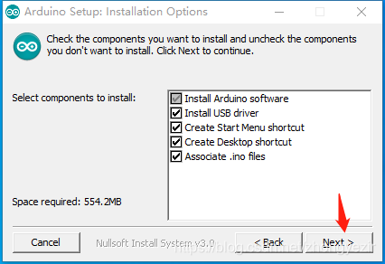
2.选择安装的文件
点击Next 下一步

3. 选择安装路径
修改安装路径

安装中。。。。
4. 安装完成

这时候我们就已经安装好Arduino软件了,但是仅仅是安装好软件,还不能编译ESP32C3相关的代码,如图

二、ArduinoIDE的ESP32C2目录导入
1. 点击Arduino文件选项,选择首选项

2. 添加开发板地址
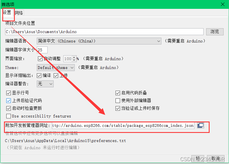
点击Arduino文件按钮,选择首选项,在附加开发板管理器网址上添加
https://raw.githubusercontent.com/espressif/arduino-ESP32/gh-pages/package_ESP32_dev_index.json
Development release link:
https://raw.githubusercontent.com/espressif/arduino-esp32/gh-pages/package_esp32_dev_index.json
Stable release link:
https://raw.githubusercontent.com/espressif/arduino-esp32/gh-pages/package_esp32_index.json
http://arduino.esp8266.com/stable/package_esp8266com_index.json
如下图,添加完成后

3. 替换原来的文件Arduino15
点击更多选项可以直接编辑下的文件目录,打开目录后关闭Arduino软件界面


以上步骤做好后重新打开Arduino软件,在工具选项选择开发板

这时候已经完成了ESP32C3的SDK包导入,下面跑一下示例看看。

三、运行开发板示例并展示效果
1. 选择一个AnalogOut的LEDSoftwareFade

程序如下,需要修改IO口2变成3(原理图是这样连接,否则硬件不匹配,灯光有所区别)

/*ledcWrite_RGB.inoRuns through the full 255 color spectrum for an rgb led Demonstrate ledcWrite functionality for driving leds with PWM on ESP32This example code is in the public domain.Some basic modifications were made by vseven, mostly commenting.*/// Set up the rgb led names
uint8_t ledR = 3;
uint8_t ledG = 4;
uint8_t ledB = 5; uint8_t ledArray[3] = {1, 2, 3}; // three led channelsconst boolean invert = true; // set true if common anode, false if common cathodeuint8_t color = 0;          // a value from 0 to 255 representing the hue
uint32_t R, G, B;           // the Red Green and Blue color components
uint8_t brightness = 255;  // 255 is maximum brightness, but can be changed.  Might need 256 for common anode to fully turn off.// the setup routine runs once when you press reset:
void setup()
{            Serial.begin(115200);delay(10); ledcAttachPin(ledR, 1); // assign RGB led pins to channelsledcAttachPin(ledG, 2);ledcAttachPin(ledB, 3);// Initialize channels // channels 0-15, resolution 1-16 bits, freq limits depend on resolution// ledcSetup(uint8_t channel, uint32_t freq, uint8_t resolution_bits);ledcSetup(1, 12000, 8); // 12 kHz PWM, 8-bit resolutionledcSetup(2, 12000, 8);ledcSetup(3, 12000, 8);
}// void loop runs over and over again
void loop()
{Serial.println("Send all LEDs a 255 and wait 2 seconds.");// If your RGB LED turns off instead of on here you should check if the LED is common anode or cathode.// If it doesn't fully turn off and is common anode try using 256.ledcWrite(1, 255);ledcWrite(2, 255);ledcWrite(3, 255);delay(2000);Serial.println("Send all LEDs a 0 and wait 2 seconds.");ledcWrite(1, 0);ledcWrite(2, 0);ledcWrite(3, 0);delay(2000);Serial.println("Starting color fade loop.");for (color = 0; color < 255; color++) { // Slew through the color spectrumhueToRGB(color, brightness);  // call function to convert hue to RGB// write the RGB values to the pinsledcWrite(1, R); // write red component to channel 1, etc.ledcWrite(2, G);   ledcWrite(3, B); delay(100); // full cycle of rgb over 256 colors takes 26 seconds}}// Courtesy http://www.instructables.com/id/How-to-Use-an-RGB-LED/?ALLSTEPS
// function to convert a color to its Red, Green, and Blue components.void hueToRGB(uint8_t hue, uint8_t brightness)
{uint16_t scaledHue = (hue * 6);uint8_t segment = scaledHue / 256; // segment 0 to 5 around the// color wheeluint16_t segmentOffset =scaledHue - (segment * 256); // position within the segmentuint8_t complement = 0;uint16_t prev = (brightness * ( 255 -  segmentOffset)) / 256;uint16_t next = (brightness *  segmentOffset) / 256;if(invert){brightness = 255 - brightness;complement = 255;prev = 255 - prev;next = 255 - next;}switch(segment ) {case 0:      // redR = brightness;G = next;B = complement;break;case 1:     // yellowR = prev;G = brightness;B = complement;break;case 2:     // greenR = complement;G = brightness;B = next;break;case 3:    // cyanR = complement;G = prev;B = brightness;break;case 4:    // blueR = next;G = complement;B = brightness;break;case 5:      // magentadefault:R = brightness;G = complement;B = prev;break;}
}
2. 选择好对应的开发板型号
选择ESP32C3 Dev Module开发板,我用的2M,开发板连接电脑选择对应端口。
3. 点击✔按钮进行编译

4. 点击➡按钮进行代码上传


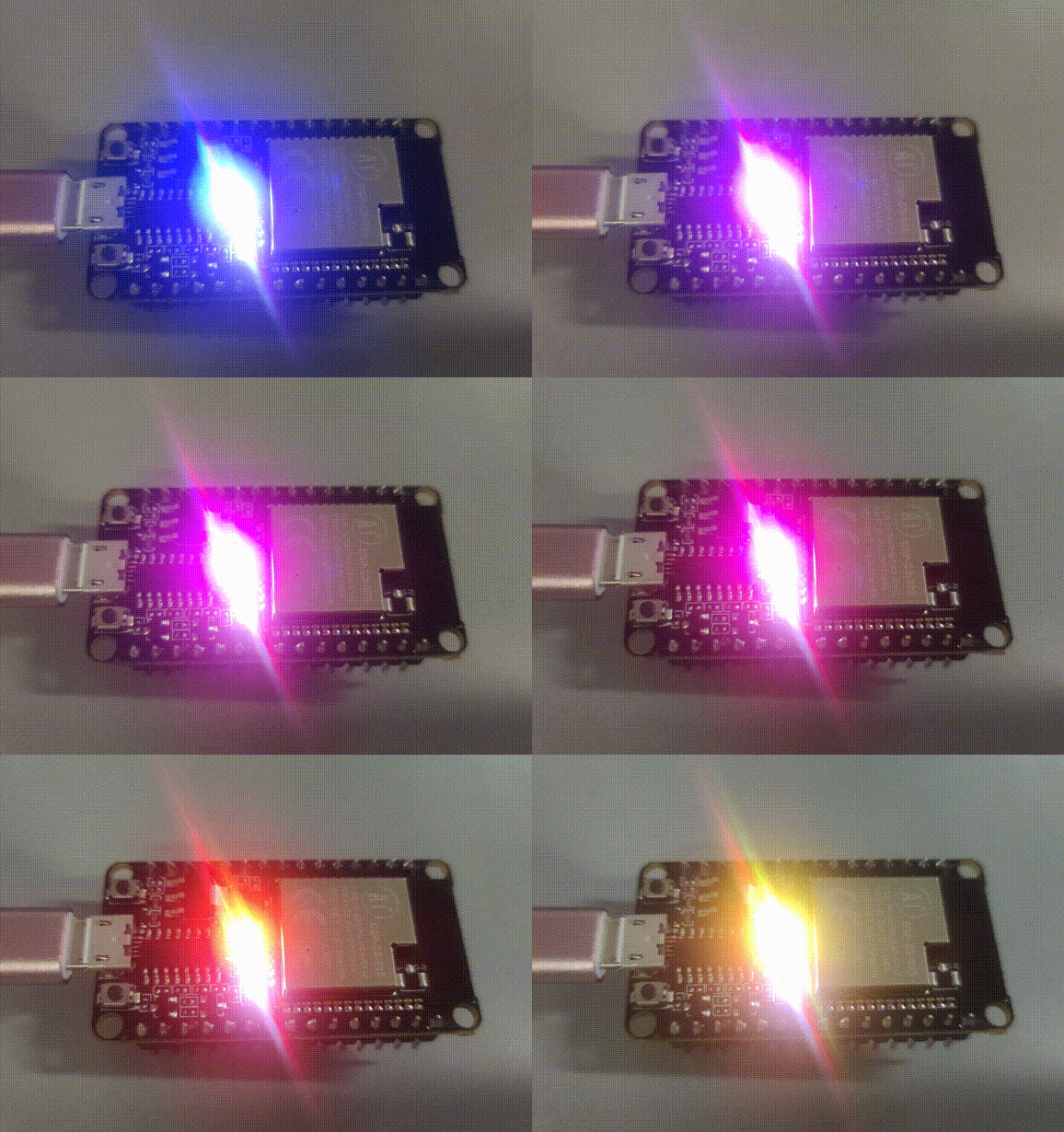
5. 实际运行的效果图

四. 小结
通过以上内容我们对基于Arduino的ESP-C3-32S-Kit 2M开发板环境搭建有了初步了解,那么尽情开发吧!在以后的博文中我们将学会用NodeMCU和arduino物联网交互使用,从而实现对外部世界进行感知,充分认识这个有机与无机的环境,科学地合理地进行创作和发挥效益,然后为人类社会发展贡献一点微薄之力。
参考文献和资料下载:
- windows下Arduino IDE搭建安信可ESP32S2系列模组开发环境(快速搭建)
- Arduino开发板库
- ESP-C3-32S-Kit 开发板规格书
-
实惠的Arduino开发板——合宙ESP32C3

这篇关于【ESP-C3-32S-Kit 2M开发板环境搭建Arduino】的文章就介绍到这儿,希望我们推荐的文章对编程师们有所帮助!


