本文主要是介绍Studio和Visualizer的对RadarSS和datapath的配置过程,希望对大家解决编程问题提供一定的参考价值,需要的开发者们随着小编来一起学习吧!
参考资料
- mmWave Demo Visualizer的cfg文件的解析(参考mmwave sdk user guide 3.4小节)
- mmWaveLink的参考文档(在SDK的安装路径下C:/ti/mmwave_sdk_03_04_00_03/packages/ti/control/mmwavelink/docs/doxygen/html/index.html)
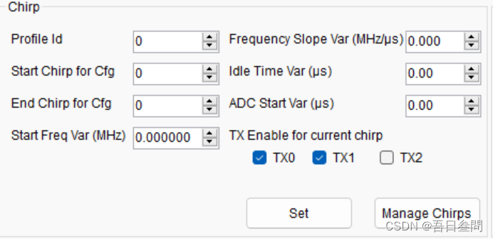
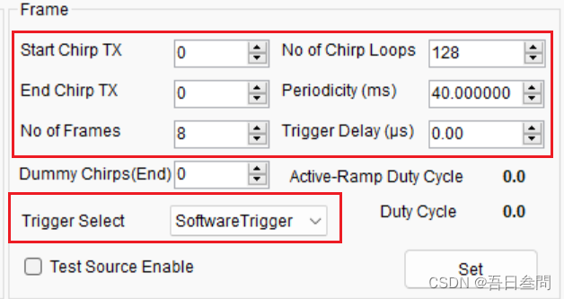
- mmWave Studio中对应的界面设置
- RF Control APIs:参考文档《Programming Chirp Parameters in TI Radar Devices》《mmWave-Radar-Interface-Control》
mmWave Demo Visualizer cfg文件的解析
从mmWave Demo Visualizer到处cfg文件,根据mmwave sdk user guide 3.4小节的内容,解析参数的具体含义,如下:
% ***************************************************************
% Created for SDK ver:03.04
% Created using Visualizer ver:3.6.0.0
% Frequency:77
% Platform:xWR16xx
% Scene Classifier:best_range_res
% Azimuth Resolution(deg):15
% Range Resolution(m):0.044
% Maximum unambiguous Range(m):9.02
% Maximum Radial Velocity(m/s):1
% Radial velocity resolution(m/s):0.13
% Frame Duration(msec):100
% RF calibration data:None
% Range Detection Threshold (dB):15
% Doppler Detection Threshold (dB):15
% Range Peak Grouping:enabled
% Doppler Peak Grouping:enabled
% Static clutter removal:disabled
% Angle of Arrival FoV: Full FoV
% Range FoV: Full FoV
% Doppler FoV: Full FoV
% ***************************************************************
sensorStop
flushCfg
dfeDataOutputMode 1
% 1-frame based chirps, 3-advanced frame config
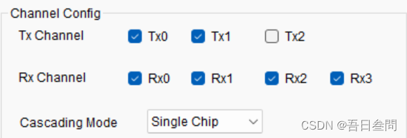
channelCfg 15 3 0
% rxChannelEn=0x1111b=15 开启接收天线Rx1-Rx4
% txChannelEn=0x11b=3    开启发射天线Tx1和Tx2
% cascading=0		 不级联
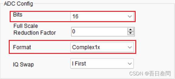
adcCfg 2 1
% numADCBits=2:0-12bit,1-14bit,2-16bit
% adcOutputFm=1: 0-real,1-complex 1x,2-complex 2x
adcbufCfg -1 0 1 1 0
% subFrameIdx=-1
% adcOutputFmt=0:0-Complex,1-Real
% SampleSwap=1:1-Q in LSB, I in MSB
% ChanInterleave=1:1 - non-interleaved
% ChirpThreshold=0
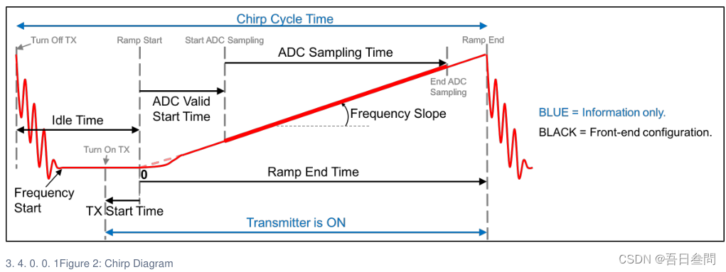
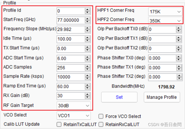
profileCfg 0 77 429 7 57.14 0 0 70 1 256 5209 0 0 30
% profileId=0
% startFreq=77GHz
% idleTime=429us
% adcStartTime=7us
% rampEndTime=57.14us
% txOutPower=0
% txPhaseShifter=0
% freqSlopeConst=70MHz/us   调制斜率
% txStartTime=1us
% numAdcSamples=256         单个chirp采样点数
% digOutSampleRate=5209ksps 采样率
%  hpfCornerFreq1=0,0-175kHz
% hpfCornerFreq2=0;0-350KHz
%  rxGain=30dB
chirpCfg 0 0 0 0 0 0 0 1
chirpCfg 1 1 0 0 0 0 0 2
% chirp start index
% chirp end index
% profile identifier 就是profileCfg中的profileId
%  start frequency variation in Hz
% frequency slope variation in kHz/us
% idle time variation in u-sec
% ADC start time variation in u-sec
% tx antenna enable mask: 1-01b-tx1 enable,2-10b-tx2 enable 设置chirp由哪个Tx发
frameCfg 0 1 16 0 100 1 0
% 使用该命令前提是dfeDataOutputMode=1,即基础帧配置模式下
% chirp start index=0 (0-511)
% chirp end index=1 (chirp start index-511)
% number of loops (1 to 255)
% number of frames (valid range is 0 to 65535, 0 means infinite)
% frame periodicity in ms
% trigger select=1:1-软件触发,2-硬件触发
% Frame trigger delay in ms
==============================暂时解析到这里
lowPower 0 1
guiMonitor -1 1 1 0 0 0 1
cfarCfg -1 0 2 8 4 3 0 15 1
cfarCfg -1 1 0 4 2 3 1 15 1
multiObjBeamForming -1 1 0.5
clutterRemoval -1 0
calibDcRangeSig -1 0 -5 8 256
extendedMaxVelocity -1 0
bpmCfg -1 0 0 1
lvdsStreamCfg -1 0 0 0
compRangeBiasAndRxChanPhase 0.0 1 0 1 0 1 0 1 0 1 0 1 0 1 0 1 0
measureRangeBiasAndRxChanPhase 0 1.5 0.2
CQRxSatMonitor 0 3 5 121 0
CQSigImgMonitor 0 127 4
analogMonitor 0 0
aoaFovCfg -1 -90 90 -90 90
cfarFovCfg -1 0 0 8.92
cfarFovCfg -1 1 -1 1.00
sensorStart
mmWaveLink的参考文档
根据功能将mmWaveLink划分为不同的Module:Device,Sensor,Data Path ,Monitoring ,Communication Protocol 。
SensorModule主要是控制毫米波前端中不同的HW block,HW block包含Chirp sequencer (Radar Timing Engine) ,Rx/Tx Channel,Rx Analog Chain,ADC and Digital Front End Configuration。

配置API可以大致分为以下几类:
- mmwave static configuration, such as: Tx and Rx channel, ADC configuration etc
- mmwave dynamic configuration, such as FMCW Chirp configuration, profile configuration
- mmwave advance configuration such as Binary phase modulation, Dynamic power save etc
- mmwave sensor control, such as: Frame start/stop
更多信息可直接参考sdk中自带的文档。
mmWave Studio中对应的界面设置
RF Control APIs
《Programming Chirp Parameters in TI Radar Devices》文档中7.2小节描述了一些API,用来配置RF参数,profile和frame。
- rlSetChannelConfig:配置发射天线和接收天线开启的数量
- rlSetAdcOutConfig:配置ADC位数和输出数据格式
- rlSetLowPowerModeConfig:设置ADC工作在低功耗模式
- rlSetProfileConfig:设置profile相关参数
- rlSetChirpConfig:设置chirp相关参数,chirp由哪个Tx发射
- rlSetFrameConfig:配置frame相关参数
这篇关于Studio和Visualizer的对RadarSS和datapath的配置过程的文章就介绍到这儿,希望我们推荐的文章对编程师们有所帮助!
