本文主要是介绍【OCC学习10】ANC101.tcl脚本解读,希望对大家解决编程问题提供一定的参考价值,需要的开发者们随着小编来一起学习吧!
在OCC的sample\tcl目录下有很多tcl脚本,是学习Draw很好的资源。本文分析一下ANC101.tcl脚本,学习基本的CAD建模方式。最终的成品见下图:
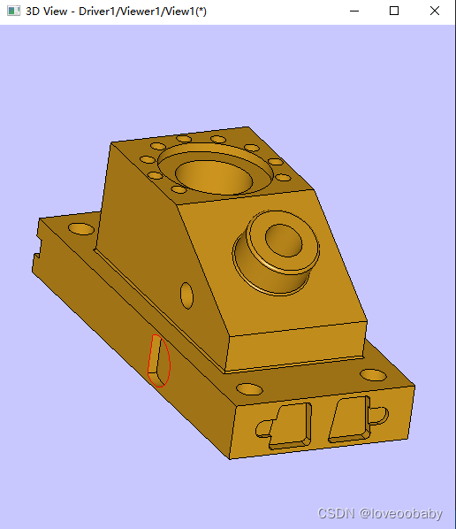
建模核心流程先创建合适的体,不断进行布尔运算得到想要的结果, 局部进行倒角操作。脚本具体分析见注释。
# The following example constructs ANC-101 object of CAM-I.
#
# This model was used as a test part for comparing modeling systems in 1979 and
# again in 1983. The tests were organized by Computer Aided Manufacturing
# International (CAM-I).
#
#Category: Modeling
#Title: ANC101 (classic test for CAD modeling from CAM-I)# 加载MODELING模块
pload MODELING# 设置参数
set my_pi 3.1415926535897931
set aModelHeight 178.25
set aPlatformLength 426.25
set aPlatformWidth 201.5
set aPlatformHeight 58.9
set aPrismLength 279
set aPrismWidth 155
set aPrismHeight [expr $aModelHeight - $aPlatformHeight]
set aPrismXOffset [expr $aPlatformLength - $aPrismLength - 69.75]
set aPrismYOffset [expr ($aPlatformWidth - $aPrismWidth)/2]######################## 第一步:创建基础box ########################################
# 创建基础box,名称为_platform
box _platform $aPlatformLength $aPlatformWidth $aPlatformHeight# Make screw holes on the platform
set aScrewHoleRadius [expr 26.2/2]
set aScrewHoleOffset 31# 创建圆柱
pcylinder _screwhole $aScrewHoleRadius $aPlatformHeight
# 对圆柱进行平移操作
ttranslate _screwhole $aScrewHoleOffset $aScrewHoleOffset 0
# 用box减去圆柱,创建孔
bcut _platform _platform _screwhole# 将圆柱复原到原点
reset _screwhole
# 圆柱平移到另一个孔处
ttranslate _screwhole [expr $aPlatformLength - $aScrewHoleOffset] $aScrewHoleOffset 0
# 减去圆柱,创建新的孔
bcut _platform _platform _screwhole
reset _screwhole
ttranslate _screwhole [expr $aPlatformLength - $aScrewHoleOffset] [expr $aPlatformWidth - $aScrewHoleOffset] 0
bcut _platform _platform _screwhole
reset _screwhole
ttranslate _screwhole $aScrewHoleOffset [expr $aPlatformWidth - $aScrewHoleOffset] 0
bcut _platform _platform _screwhole
reset _screwhole################## 第二步:侧面挖槽 #####################
set aCaveLength 81.38
set aCaveDepth 10
set aCaveWidth 19.38
set aBottomLevel [expr $aPlatformHeight/2 - $aCaveWidth/2]
set aTopLevel [expr $aPlatformHeight/2 + $aCaveWidth/2]
# 创建一个贝塞尔曲线
beziercurve t_bcurve 4  0 $aCaveLength $aBottomLevel  3  0 [expr $aCaveLength + $aCaveWidth/2] $aBottomLevel 6  0 [expr $aCaveLength + $aCaveWidth/2] $aTopLevel 6  0 $aCaveLength $aTopLevel 3
vertex t_v1 0 $aCaveLength $aBottomLevel
vertex t_v2 0 $aCaveLength $aTopLevel
# 使用创建的贝塞尔曲线创建边
mkedge t_e1 t_bcurve
# 创建了一条直边
edge t_e2 t_v1 t_v2
# 将创建的直边与使用贝塞尔曲线的边合并成wire
wire t_w t_e1 t_e2
# 使用wire创建面
mkplane t_f1 t_w
# 将面按矢量($aCaveDepth 0 0)进行拉伸成体
prism t_s1 t_f1 $aCaveDepth 0 0
# 创建一个新的box
box t_s2 0 0 $aBottomLevel $aCaveDepth $aCaveLength $aCaveWidth
# 将创建的box与拉伸体合并
bfuse _backcave t_s1 t_s2
# 进行布尔运算,开槽
bcut _platform _platform _backcave######## 第三步:右侧开槽 ###########
# 创建一个圆,trim形成大半圆,并创建edge
set aRCaveRadius 26.2
set aRCaveDistToSection 15.5
set aCurveParam [expr ($my_pi - acos($aRCaveDistToSection/$aRCaveRadius))]
set aRCaveCenterX [expr $aPlatformLength - 162.75]
set aRCaveCenterZ [expr $aPlatformHeight/2]
circle t_circle $aRCaveCenterX 0 $aRCaveCenterZ 0 1 0 1 0 0 $aRCaveRadius
trim t_curve t_circle -$aCurveParam $aCurveParam
mkedge t_e1 t_curve
# 提取半圆的两端顶点,并创建直线段
cvalue t_curve -$aCurveParam t_x t_y t_z
vertex t_v1 t_x t_y t_z
cvalue t_curve $aCurveParam t_x t_y t_z
vertex t_v2 t_x t_y t_z
edge t_e2 t_v1 t_v2# 形成wire
wire t_w t_e1 t_e2
mkplane t_f t_w
prism t_s t_f 0 $aCaveDepth 0
# 布尔运算进行开槽
bcut _platform _platform t_s################## 第四步:前面进行剪切 #######################################
# 创建4个2d圆
set aFCaveCirclesRadius 4.65
set aFCaveBottomWidth 37.8
set aFCaveHeight 38.75
set aFCaveTopWidth 27
set aFCaveSmallCircleRadius 9.3
circle t_circle1 [expr $aFCaveTopWidth/2] [expr $aFCaveHeight/2] $aFCaveCirclesRadius
circle t_circle2 [expr -$aFCaveTopWidth/2] [expr $aFCaveHeight/2] $aFCaveCirclesRadius
circle t_circle3 [expr -$aFCaveBottomWidth/2] [expr -$aFCaveHeight/2] $aFCaveCirclesRadius
circle t_circle4 [expr $aFCaveBottomWidth/2] [expr -$aFCaveHeight/2] $aFCaveCirclesRadius# 创建与两个圆相切的线,一共有4条, 选取其中一条进行参数trim
lintan t_l t_circle1 t_circle2
trim t_side1 t_l_1 0 $aFCaveTopWidthlintan t_l t_circle2 t_circle3
trim t_side2 t_l_1 0 39.058577803089555lintan t_l t_circle3 t_circle4
trim t_side3 t_l_1 0 $aFCaveBottomWidthlintan t_l t_circle4 t_circle1
trim t_side4 t_l_1 0 39.196587861700415trim t_circle1 t_circle1 0.15109758878146562 1.5707963267948966
trim t_circle2 t_circle2 1.5707963267948966 3.0158086349284448
trim t_circle3 t_circle3 3.0158086349284448 4.7123889803846897
trim t_circle4 t_circle4 4.7123889803846897 0.15109758878146562 plane t_plane 0 0 0 1 0 0 0 1 0to3d t_circle1 t_circle1 t_plane
to3d t_circle2 t_circle2 t_plane
to3d t_circle3 t_circle3 t_plane
to3d t_circle4 t_circle4 t_plane
to3d t_side1 t_side1 t_plane
to3d t_side2 t_side2 t_plane
to3d t_side3 t_side3 t_plane
to3d t_side4 t_side4 t_planemkedge t_e1 t_circle1
mkedge t_e2 t_side1
mkedge t_e3 t_circle2
mkedge t_e4 t_side2
mkedge t_e5 t_circle3
mkedge t_e6 t_side3
mkedge t_e7 t_circle4
mkedge t_e8 t_side4wire t_w t_e1 t_e2 t_e3 t_e4 t_e5 t_e6 t_e7 t_e8
mkplane t_f t_w
# 最终拉伸成体
prism t_s1 t_f -$aCaveDepth 0 0circle t_circle 0 [expr $aFCaveTopWidth/2 + $aFCaveBottomWidth/2] 0 1 0 0 $aFCaveSmallCircleRadius
mkedge t_e t_circle
wire t_w t_e
mkplane t_f t_w
prism t_s2 t_f [expr -$aCaveDepth/2] 0 0box t_s3 0 0 -$aFCaveSmallCircleRadius  [expr -$aCaveDepth/2] [expr $aFCaveTopWidth/2 + $aFCaveBottomWidth/2] [expr $aFCaveSmallCircleRadius*2]# Compile elements
bfuse t_s2 t_s2 t_s3
bfuse _frontcave t_s1 t_s2
unifysamedom _frontcave _frontcave# Cut this cave from the platform
ttranslate _frontcave $aPlatformLength [expr $aPlatformWidth*2/3] [expr $aPlatformHeight/2]
bcut _platform _platform _frontcave# 镜像出另一面
tmirror _frontcave $aPlatformLength [expr $aPlatformWidth/2] [expr $aPlatformHeight/2] 0 1 0
bcut _platform _platform _frontcave#=====================第五步:创建上部楔形体 ===========================================================
# A wedge on the platform
box t_box  $aPrismXOffset $aPrismYOffset $aPlatformHeight $aPrismLength $aPrismWidth $aPrismHeightset aCutwedgeLength [expr $aPrismHeight/0.57735]
wedge _cutwedge $aPlatformLength [expr $aPrismYOffset + $aPrismWidth] $aModelHeight 0 -1 0 -1 0 0 $aCutwedgeLength $aPrismHeight $aPrismWidth 0bcut _prism t_box _cutwedge#======================第六步:在楔形体上部创建9个空=============================================
set aWedgeSmallHolesRadius 7.68
set aWedgeSmallHolesOrbit 67.81
set aWedgeHoleXPos [expr $aPrismXOffset + 77.5]
set aWedgeHoleYPos [expr $aPrismYOffset + 77.5]plane t_plane $aWedgeHoleXPos $aWedgeHoleYPos [expr $aPlatformHeight + $aPrismHeight/2] 0 0 1 1 0 0
pcylinder t_cyl t_plane $aWedgeSmallHolesRadius [expr $aPrismHeight/2]set i 2
while {$i <= 10} {ttranslate t_cyl [expr $aWedgeSmallHolesOrbit*cos($i*$my_pi/6)] [expr $aWedgeSmallHolesOrbit*sin($i*$my_pi/6)] 0; bcut _prism _prism t_cyl; reset t_cyl; incr i}#====================== 第七步:在楔形体上部创建圆柱,并倒角,开洞 与下部进行合并 =================================
# Make a cylinder on a canted side
set aWedgeCylinderRadius 38.75
set aWedgeCylinderHeight 38.75
set aWedgeCantedHeight [expr tan($my_pi/6)*($aCutwedgeLength - 69.75)]
set aWedgeCylinderZPos [expr $aModelHeight - $aWedgeCantedHeight/2]
plane t_plane [expr $aPrismXOffset + $aPrismLength*3/4] [expr $aPrismYOffset + $aPrismWidth/2] $aWedgeCylinderZPos cos($my_pi/3) 0 sin($my_pi/3) 0 1 0
pcylinder t_cyl t_plane $aWedgeCylinderRadius $aWedgeCylinderHeight
# 将圆柱炸开,提取边
explode t_cyl e
# 对边进行倒角
blend t_cyl t_cyl 3 t_cyl_1
# 对上部物体进行合并
bfuse _prism _prism t_cyl
unifysamedom _prism _prism# Make a hole in the cylinder on the wedge
pcylinder t_cyl t_plane [expr $aWedgeCylinderRadius/2] 100
ttranslate t_cyl [expr -60*cos($my_pi/3)] 0 [expr -60*sin($my_pi/3)]
bcut _prism _prism t_cylplane t_plane [expr $aPlatformLength - 162.75] $aPrismYOffset [expr $aModelHeight - $aWedgeCantedHeight] 0 1 0 1 0 0
pcylinder t_cyl t_plane 13.1 [expr $aPrismWidth/2]
bcut _prism _prism t_cyl# Fuse the platform and the prism
bfuse _model _platform _prism#====================== 第八步:创建上下贯通的孔 =================================
# 通过创建两个圆柱,进行布尔运算创建孔
set aWedgeHoleInnerRadius 38.77
set aWedgeHoleOuterRadius 58.13
set aWedgeHoleBottomInnerRadius 50.38# Cylinders from bottom to top
plane t_plane $aWedgeHoleXPos $aWedgeHoleYPos 0
pcylinder t_cyl1 t_plane $aWedgeHoleOuterRadius 10
pcylinder t_cyl2 t_plane $aWedgeHoleBottomInnerRadius 10
pcylinder t_cyl3 t_plane $aWedgeHoleInnerRadius [expr $aModelHeight - 30]
pcylinder t_cyl4 t_plane $aWedgeHoleOuterRadius 10ttranslate t_cyl2 0 0 10
ttranslate t_cyl3 0 0 20
ttranslate t_cyl4 0 0 [expr $aModelHeight - 10]bfuse _cutCylindricShape t_cyl1 t_cyl2
bfuse _cutCylindricShape _cutCylindricShape t_cyl3
bfuse _cutCylindricShape _cutCylindricShape t_cyl4bcut _model _model _cutCylindricShape#====================== 第八步:创建上下贯通的孔 ========================
# Add a block on left side
circle t_circle1 0 0 38.75
circle t_circle2 [expr 38.75 + 9.3] [expr -57.35 + 9.3] 9.3
circle t_circle3 [expr -38.75 - 9.3] [expr -57.35 + 9.3] 9.3lintan t_l t_circle1 t_circle2
trim t_line12 t_l_2 0 48.05lintan t_l t_circle2 t_circle3
trim t_line23 t_l_3 0 96.1lintan t_l t_circle3 t_circle1
trim t_line31 t_l_4 0 48.05trim t_circle1 t_circle1 0 $my_pi
trim t_circle2 t_circle2 $my_pi 4.7123889803846897
trim t_circle3 t_circle3 4.7123889803846897 6.2831853071795862reverse t_circle1plane t_plane [expr $aPrismXOffset + 77.5] [expr $aPrismYOffset + $aPrismWidth] [expr $aPlatformHeight + 57.35] 0 1 0 -1 0 0to3d t_circle1 t_circle1 t_plane
to3d t_circle2 t_circle2 t_plane
to3d t_circle3 t_circle3 t_plane
to3d t_line12 t_line12 t_plane
to3d t_line23 t_line23 t_plane
to3d t_line31 t_line31 t_planemkedge t_e1 t_circle1
mkedge t_e2 t_line31
mkedge t_e3 t_circle3
mkedge t_e4 t_line23
mkedge t_e5 t_circle2
mkedge t_e6 t_line12wire t_w t_e1 t_e2 t_e3 t_e4 t_e5 t_e6
mkplane t_f t_w
prism t_s t_f 0 $aCaveDepth 0bfuse _model _model t_s#====================== 第九步:进行局部倒角 ========================
# Make fillets
explode _model e# Make a weld at joint edges of platform and wedge
blend _model _model 2 _model_27
blend _model _model 2 _model_28
blend _model _model 2 _model_29
blend _model _model 2 _model_30
blend _model _model 2 _model_32# Cylinder on wedge
blend result _model 2 _model_161# Show result
pload VISUALIZATION
vinit Driver1/Viewer1/View1
vbackground -color C8C8FF
vdisplay -dispMode 1 result
vfit
# 控制绘制边(mostContinuity这个选项开发文档没有写)
vaspects result -setFaceBoundaryDraw 1 -mostContinuity c2
命令总结:
- 二维曲线在3d视图是不会显示的,需使用2d视图进行显示;
- 由点构成边,再构建wire,进一步创建面,最总拉伸成体;
-
vaspects可以控制绘制边
这篇关于【OCC学习10】ANC101.tcl脚本解读的文章就介绍到这儿,希望我们推荐的文章对编程师们有所帮助!


