本文主要是介绍c语言温度报警系统_温度警报系统,希望对大家解决编程问题提供一定的参考价值,需要的开发者们随着小编来一起学习吧!
c语言温度报警系统
目标-建立温度警报系统项目 (Aim -Build a project for temperature alert system)
二手硬件 - (Hardware Used -)

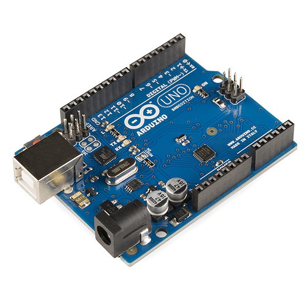
1. Arduino Uno R3 (1)
1. Arduino Uno R3(1)
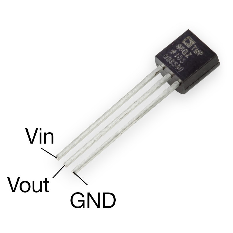
2. Temperature Sensor (TMP36) (1)
2.温度传感器(TMP36)(1)
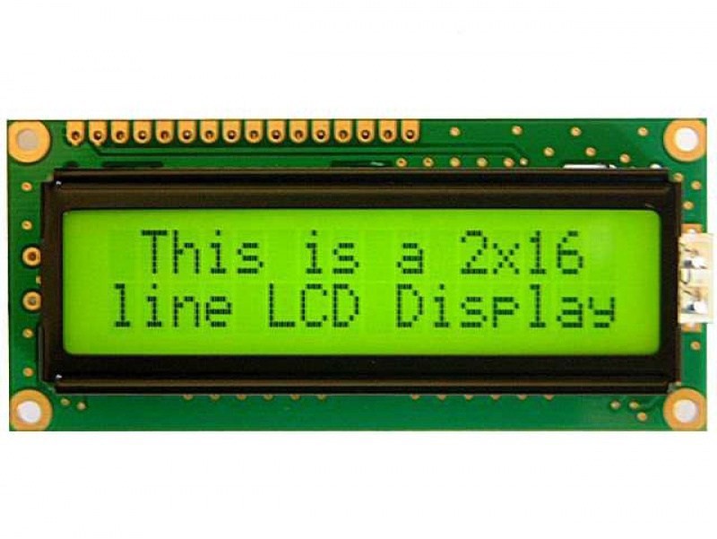
3. LCD 16x2 (1)
3. LCD 16x2(1)
4. 250kΩ Potentiometer (1)
4.250kΩ电位器(1)
5. 220Ω Resistor (1)
5.220Ω电阻(1)
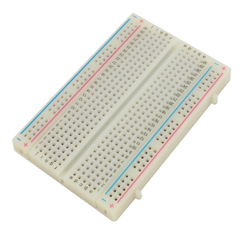
6. Bread Board
6.面包板
使用的软件- (Software Used -)
Arduino IDE or ThinkerCad (Online web based Simulator)
Arduino IDE或ThinkerCad(基于网络的在线模拟器)
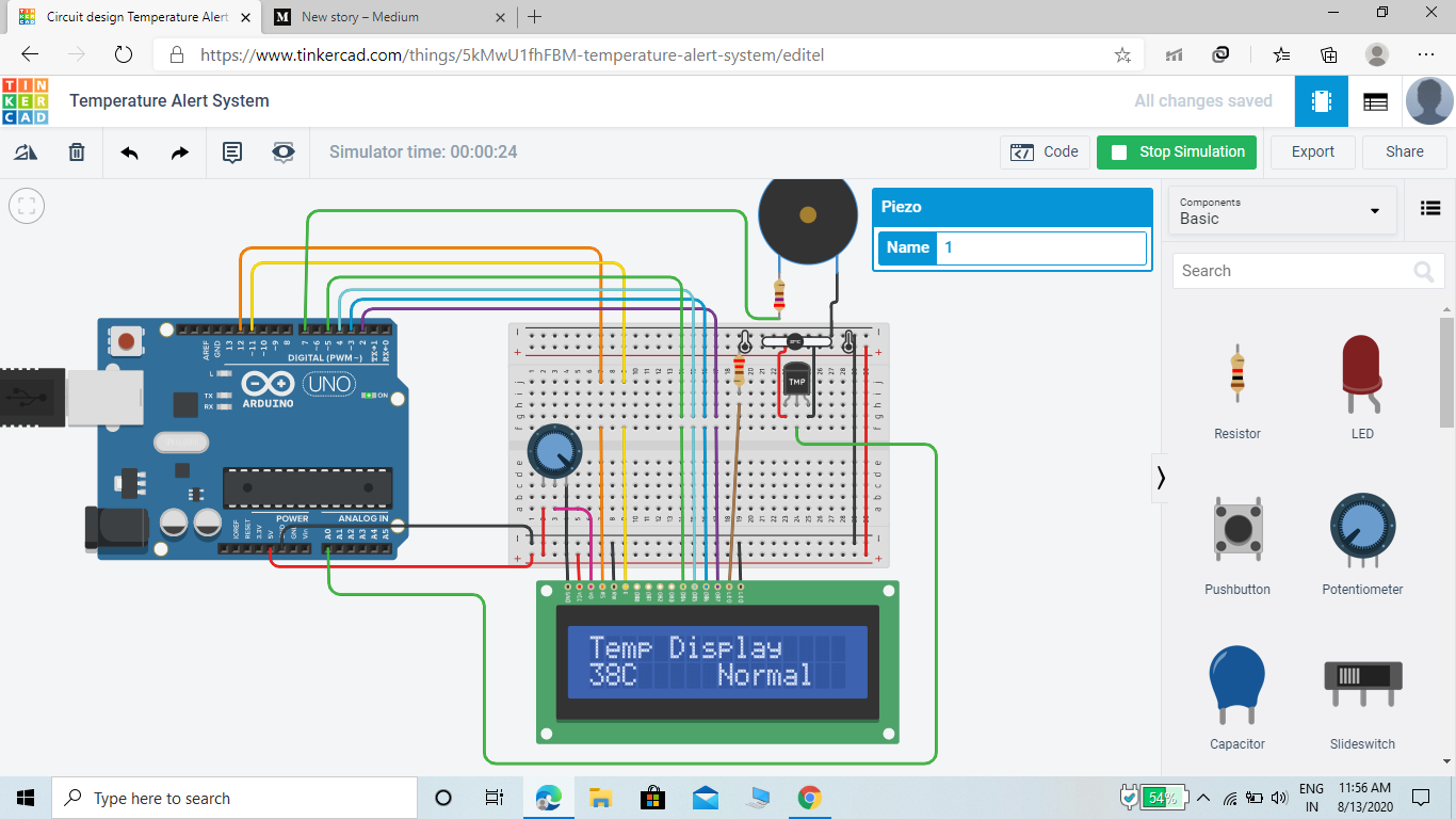
电路原理图 - (Circuit Diagram -)


说明 (Explanation)
Hello Everyone!
大家好!
Myself Rahul Jat pursuing B.Tech from Government Engineering College Bikaner currently working on different IOT , Embedded and Robotics Projects , carrying out a project to demonstrate how we can simulate a Temperature Alert System by temperature sensor, lcd 16*2 , Piezo Buzzer and an Arduino UNO R3 using Tinkercad .
我自己的Rahul Jat从Bikaner政府工程学院攻读B.Tech,目前从事不同的IOT,嵌入式和机器人项目,并执行一个项目来演示如何通过温度传感器,lcd 16 * 2,Piezo Buzzer和使用Tinkercad的Arduino UNO R3。
Temperature sensors and LCD can serve as a simple mechanism in different situations such as room temperature monitoring and even plant monitoring or any place that considers temperature as an important element!
温度传感器和LCD可以在不同情况下用作简单的机制,例如室温监控甚至工厂监控或任何将温度视为重要因素的地方!
I am using it as a alert system to get notified when the temperature is above 50 Degree Celsius alarm will go on and a specific tone will be given as output for notification and the LCD 16*2 will show the temperature with the situation as Normal, Cold or Too hot.
我将其用作警报系统,以便在温度高于50摄氏度时发出警报,并且会发出特定的提示音作为通知输出,并且LCD 16 * 2将以正常状态显示温度,太冷或太热。
I am using Thinkercad.Tinkercad provides pre-built circuits that can help users to not complicate their circuits by building from scratch.
我正在使用Thinkercad.Tinkercad提供了预先构建的电路,可以帮助用户从头开始构建而不使电路复杂化。
In the Circuit Desinger, we can search for lcd, which will show that there is a starter circuit that has a pre-connected circuit between an Arduino and LCD.
在Circuit Desinger中,我们可以搜索lcd,这将显示一个启动器电路,该电路在Arduino和LCD之间预先连接了电路。
In Tinkercad, there is only one temperature sensor available, which is the TMP36.
在Tinkercad中,只有一个温度传感器可用,即TMP36。
The TMP36 does not have a temperature sensitive resistor. Instead this sensor uses the property of diodes; as a diode changes temperature the voltage changes with it at a known rate. The sensor measures the small change and outputs an analog voltage between 0 and 1.75VDC based on it. To obtain the temperature, we need to measure the output and perform some calculation to convert it to degree celsius.
TMP36没有温度敏感电阻。 取而代之的是,该传感器利用了二极管的特性。 当二极管改变温度时,电压以已知的速率变化。 传感器测量微小变化,并基于此输出介于0和1.75VDC之间的模拟电压。 为了获得温度,我们需要测量输出并执行一些计算以将其转换为摄氏度。
The TMP36 has 3 pins, which can be easily identified by noticing the flat side of the sensor.
TMP36具有3个引脚,可以通过注意传感器的扁平侧来轻松识别。
The first pin is the +5V pin which will be connected to the supply.
第一个引脚是+ 5V引脚,它将连接到电源。
The second pin is the Vout which will be connected to the Analog In pin, (could be A0-A5). I used A0 for this project.
第二个引脚是Vout,它将连接到模拟输入引脚(可以是A0-A5)。 我为此项目使用了A0。
The third pin is the GND pin which will be connected to the ground of the Arduino.
第三个引脚是GND引脚,它将连接到Arduino的地面。
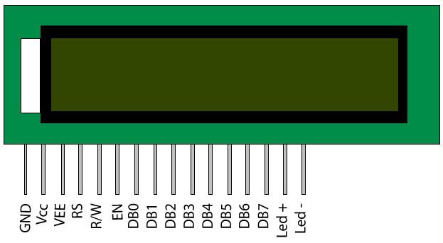
Interfacing LCD 16*2
液晶屏接口16 * 2
Liquid crystal displays (LCDs) are a commonly used to display data in devices such as calculators, microwave ovens, and many other electronic devices..
液晶显示器(LCD)通常用于在诸如计算器,微波炉和许多其他电子设备之类的设备中显示数据。
In this tutorial, I will show you how to use a 16x2 LCD with an Arduino. The 16x2 LCD used in this experiment has a total of 16 pins. As shown in the table below, eight of the pins are data lines (pins 7–14), two are for power and ground (pins 1 and 16), three are used to control the operation of LCD (pins 4–6), and one is used to adjust the LCD screen brightness (pin 3). The remaining two pins (15 and 16) power the backlight.The details of the LCD terminals are as follows:
在本教程中,我将向您展示如何在Arduino上使用16x2 LCD。 本实验中使用的16x2 LCD共有16个引脚。 如下表所示,八个引脚是数据线(引脚7–14),两个用于电源和接地(引脚1和16),三个用于控制LCD的操作(引脚4–6),一种用于调节LCD屏幕的亮度(引脚3)。 其余两个引脚(15和16)为背光灯供电.LCD端子的详细信息如下:
Terminal 1 - GND
端子1-GND
Terminal 2 - +5V
端子2-+ 5V
Terminal 3 - Mid terminal of potentiometer (for brightness control)
端子3-电位计的中间端子(用于亮度控制)
Terminal 4 - Register Select (RS)
终端4-寄存器选择(RS)
Terminal 5 - Read/Write (RW)
航站楼5-读/写(RW)
Terminal 6 - Enable (EN)
终端6-启用(EN)
Terminal 7 - DB0
航站楼7-DB0
Terminal 8 - DB1
航站楼8-DB1
Terminal 9 - DB2
9号客运大楼-DB2
Terminal 10 - DB3
10号客运大楼-DB3
Terminal 11- DB4
航站楼11- DB4
Terminal 12 - DB5
航站楼12-DB5
Terminal 13 - DB6
13号客运大楼-DB6
Terminal 14 - DB7
14号航站楼-DB7
Terminal 15 - +4.2–5V
端子15-+ 4.2–5V
Terminal 16 - GND
端子16-GND
Now Pins which i used to connect my LCD can be seen from the Circuit Diagram.
现在,从电路图中可以看到用于连接LCD的引脚。
使用的代码- (CODE USED -)
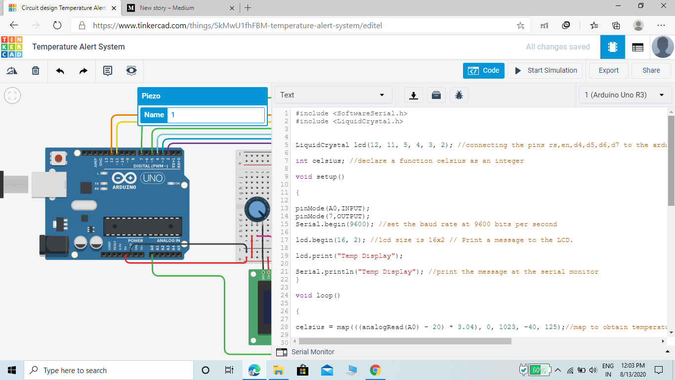
// include the library code:#include <LiquidCrystal.h>
//包含库代码:#include <LiquidCrystal.h>
#include <SoftwareSerial.h>
#include <SoftwareSerial.h>
LiquidCrystal lcd(12, 11, 5, 4, 3, 2); //connecting the pins rs,en,d4,d5,d6,d7 to the arduino at pin 12 11 5 4 3 2
液晶LCD(12,11,5,4,4,3,2); //将rs,en,d4,d5,d6,d7引脚连接到arduino的引脚12 11 5 4 3 2
int celsius; //declare a function celsius as an integer
摄氏度 //将函数celsius声明为整数
void setup()
无效setup()
{
{
pinMode(A0,INPUT);
pinMode(A0,INPUT);
pinMode(7,OUTPUT);
pinMode(7,输出);
Serial.begin(9600); //set the baud rate at 9600 bits per second
Serial.begin(9600); //将波特率设置为每秒9600位
lcd.begin(16, 2); //lcd size is 16x2 // Print a message to the LCD.
lcd.begin(16,2); // lcd大小为16x2 // //将消息打印到LCD。
lcd.print(“Temp Display”);
lcd.print(“临时显示”);
Serial.println(“Temp Display”); //print the message at the serial monitor
Serial.println(“临时显示”); //在串行监视器上打印消息
}
}
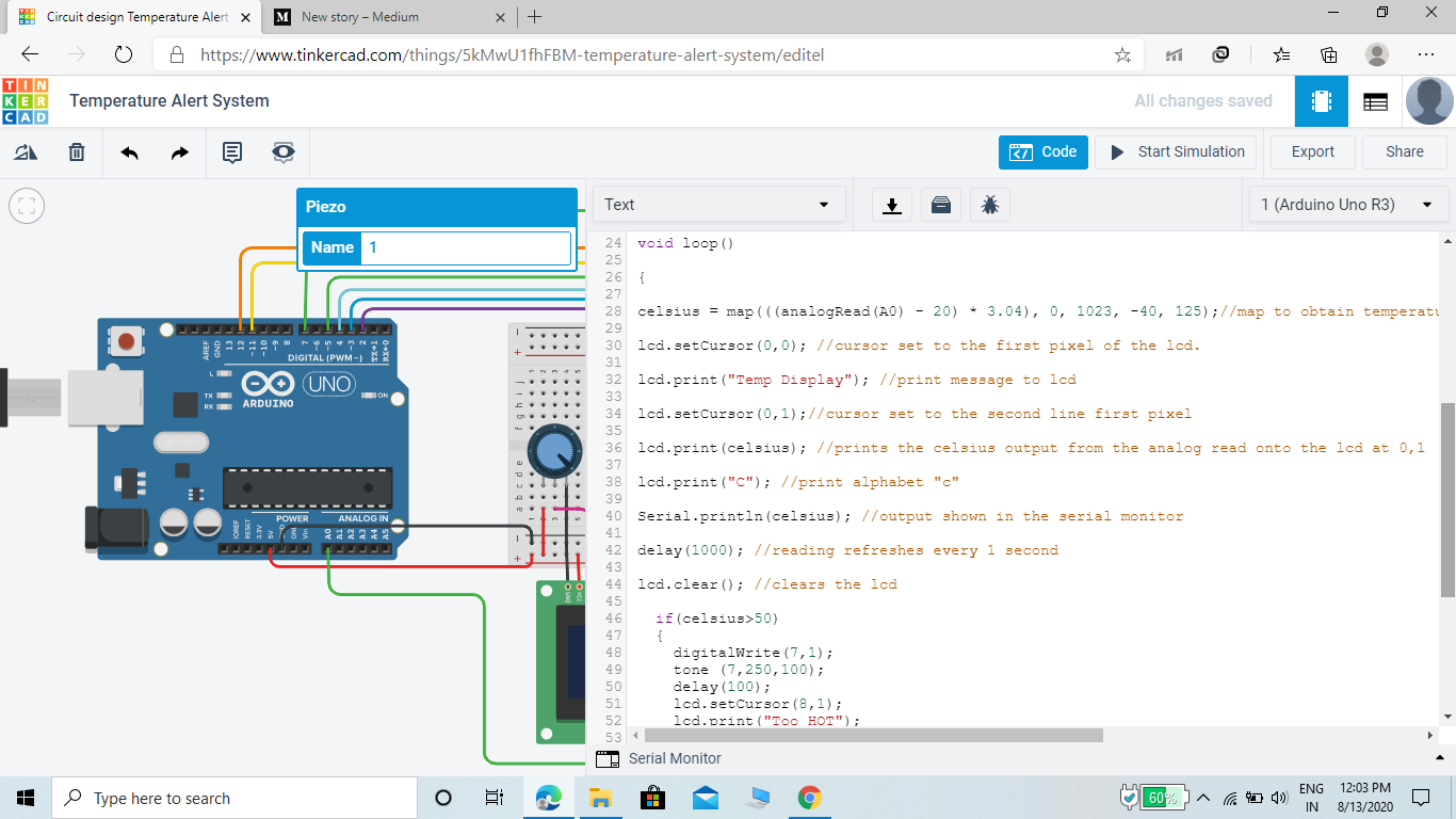
void loop()
无效循环()
{
{
celsius = map(((analogRead(A0) — 20) * 3.04), 0, 1023, -40, 125);//map to obtain temperature mathematically.Meaning 0 = -40degrees and 1023 = 125degrees
celsius = map((((analogRead(A0)— 20)* 3.04),0,1023,-40,125); //映射以数学方式获得温度。意思是0 = -40度和1023 = 125度
lcd.setCursor(0,0); //cursor set to the first pixel of the lcd.
lcd.setCursor(0,0); //将光标设置为LCD的第一个像素。
lcd.print(“Temp Display”); //print message to lcd
lcd.print(“临时显示”); //将消息打印到lcd
lcd.setCursor(0,1);//cursor set to the second line first pixel
lcd.setCursor(0,1); //将光标设置为第二行的第一个像素
lcd.print(celsius); //prints the celsius output from the analog read onto the lcd at 0,1
lcd.print(摄氏度); //将模拟读取的摄氏温度输出打印到LCD上的0,1
lcd.print(“C”); //print alphabet “c”
lcd.print(“ C”); //打印字母“ c”
Serial.println(celsius); //output shown in the serial monitor
Serial.println(摄氏); //输出显示在串行监视器中
delay(1000); //reading refreshes every 1 second
延迟(1000); //每1秒钟刷新一次
lcd.clear(); //clears the lcd
lcd.clear(); //清除液晶
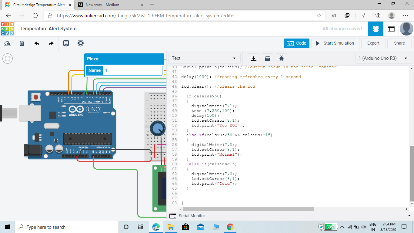
if(celsius>50) { digitalWrite(7,1); tone (7,250,100); delay(100); lcd.setCursor(8,1); lcd.print(“Too HOT”); } else if(celsius<50 && celsius>=15) { digitalWrite(7,0); lcd.setCursor(8,1); lcd.print(“Normal”); } else if(celsius<15) { digitalWrite(7,0); lcd.setCursor(8,1); lcd.print(“Cold”); }
if(摄氏度> 50){digitalWrite(7,1); 音调(7,250,100); 延迟(100); lcd.setCursor(8,1); lcd.print(“太热”); } else if(celsius <50 && celsius> = 15){digitalWrite(7,0); lcd.setCursor(8,1); lcd.print(“普通”); } else if(摄氏<15){digitalWrite(7,0); lcd.setCursor(8,1); lcd.print(“冷”); }
}
}
结果 (RESULT)
When start simulation the TMP36 sense temperature and show on LCD.
开始仿真时,TMP36感应温度并在LCD上显示。
When the Temperature increases and reached above 50 the Piezo Buzzer will Turn on and produce a specific tone used in code which shows our alert system goes on after reaching specified temperature.
当温度升高并达到50以上时,压电蜂鸣器将打开并产生代码中使用的特定提示音,表明我们的警报系统在达到指定温度后会继续工作。
Also LCD shows condition i.e “Too Hot”.
LCD也显示状态,即“太热”。
下一步是什么! (WHATS NEXT!)
Use a ESP8266 Wifi module to send the data of temperature to the Thingspeak Cloud. And can use ThingTweet to Tweet automatically when temperature reach above 50 or can create a messenger bot which will notify you through messenger messages about the condition.
使用ESP8266 Wifi模块将温度数据发送到Thingspeak Cloud。 并且可以在温度达到50以上时使用ThingTweet自动鸣叫,也可以创建一个Messenger机器人,该机器人将通过Messenger消息通知您有关情况。
Since Thinkercad does not have ESP module so can’t show this project now but will try to show through practical hardware after a while.
由于Thinkercad没有ESP模块,因此现在无法显示此项目,但过一会儿将尝试通过实用的硬件进行显示。
翻译自: https://medium.com/@rahuljat4158/temperature-alert-system-da293034f62f
c语言温度报警系统
相关文章:
这篇关于c语言温度报警系统_温度警报系统的文章就介绍到这儿,希望我们推荐的文章对编程师们有所帮助!


