本文主要是介绍loopback地址,静态vlan,trunk的介绍,附实验题,希望对大家解决编程问题提供一定的参考价值,需要的开发者们随着小编来一起学习吧!
目录
- Loopback地址
- 静态vlan
- 1.vlan概述与优势
- 2.vlan的范围
- 3.静态VLAN的配置
- Trunk
- 实验题
- 实验一
- 实验二
- 实验三
Loopback地址
loopback地址是路由器的逻辑接口,用来模拟网络环境。逻辑接口在查询时不显示。
loopback接口的配置命令是
[R1]int loop
[R1 ]int LoopBack 0
[R1- LoopBack0]ip add “ip地址” “子网掩码”
静态vlan
1.vlan概述与优势
vlan工作于数据链路层,通过在交换机中接入VLAN,加入VLAN,相互的VLAN用来隔离广播域。vlan可以控制广播,增强网络安全性,简化网络管理。静态vlan基于端口划分vlan。
2.vlan的范围
| vlan范围 | 范围 | 用途 |
|---|---|---|
| 1 | 正常 | 默认VLAN |
| 2-1001 | 正常 | 用于以太网的vlan,用户可以创建、使用和删除这些VLAN |
| 1002-1005 | 正常 | 用于FDDI和令牌环的默认VLAN,用户不能删除这些VLAN |
| 1006-1024 | 保留 | 仅限系统使用,用户不能查看和使用这些VLAN |
| 1025-4094 | 扩展 | 仅用于以太网VLAN |
3.静态VLAN的配置
1.创建VLAN
2.将交换机的端口加入到相应的VLAN中
3.验证VLAN的配置
Trunk
Trunk为每一个vlan提供一条链路,在交换网络中起到接入链路,中继链路的作用。
实验题
实验一
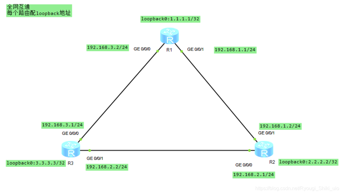
R1配置
<Huawei>sys
Enter system view, return user view with Ctrl+Z.
[Huawei]sys R1
[R1]interface g0/0/0
[R1-GigabitEthernet0/0/0]ip address 192.168.3.2 24
[R1-GigabitEthernet0/0/0]interface g0/0/1
[R1-GigabitEthernet0/0/1]ip address 192.168.1.1 24
[R1-GigabitEthernet0/0/1]
[R1-GigabitEthernet0/0/1]q
[R1]interface LoopBack 0
[R1-LoopBack0]ip address 1.1.1.1 32
interface LoopBack0ip address 1.1.1.1 255.255.255.255
return
[R1-LoopBack0]q
[R1]ip route-
[R1]ip route-static 2.2.2.2 32 192.168.1.2
[R1]ip route-static 3.3.3.3 32 192.168.3.1
R2配置
<Huawei>sys
Enter system view, return user view with Ctrl+Z.
[Huawei]sys R2
[R2]interface g0/0/0
[R2-GigabitEthernet0/0/0]ip address 192.168.2.1 24
Apr  6 2021 14:20:02-08:00 R2 %%01IFNET/4/LINK_STATE(l)[0]:The line protocol IP
on the interface GigabitEthernet0/0/0 has entered the UP state.
[R2-GigabitEthernet0/0/0]interface g0/0/1
[R2-GigabitEthernet0/0/1]ip address 192.168.1.2 24
Apr  6 2021 14:20:24-08:00 R2 %%01IFNET/4/LINK_STATE(l)[1]:The line protocol IP
on the interface GigabitEthernet0/0/1 has entered the UP state.
[R2-GigabitEthernet0/0/1]q
[R2]interface loopback 0
[R2-LoopBack0]ip address 2.2.2.2 32
interface LoopBack0ip address 2.2.2.2 255.255.255.255
[R2-LoopBack0]q
[R2]ip route-
[R2]ip route-static 1.1.1.1 32 192.168.1.1
[R2]ip route-
[R2]ip route-static 3.3.3.3 32 192.168.2.2
R3配置
<Huawei>sys
Enter system view, return user view with Ctrl+Z.
[Huawei]sys R3
[R3]interface g0/0/0
[R3-GigabitEthernet0/0/0]ip address 192.168.3.1 24
Apr  6 2021 14:20:59-08:00 R3 %%01IFNET/4/LINK_STATE(l)[0]:The line protocol IP
on the interface GigabitEthernet0/0/0 has entered the UP state.
[R3-GigabitEthernet0/0/0]interface g0/0/1
[R3-GigabitEthernet0/0/1]ip address 192.168.2.2 24
[R3-GigabitEthernet0/0/1]
Apr  6 2021 14:21:21-08:00 R3 %%01IFNET/4/LINK_STATE(l)[1]:The line protocol IP
on the interface GigabitEthernet0/0/1 has entered the UP state.
[R3-GigabitEthernet0/0/1]q
[R3]interface loopback 0
[R3-LoopBack0]ip address 3.3.3.3 32
interface LoopBack0ip address 3.3.3.3 255.255.255.255
[R3-LoopBack0]q
[R3]ip route-static 1.1.1.1 32 192.168.3.2
[R3]ip route-static 2.2.2.2 32 192.168.2.1
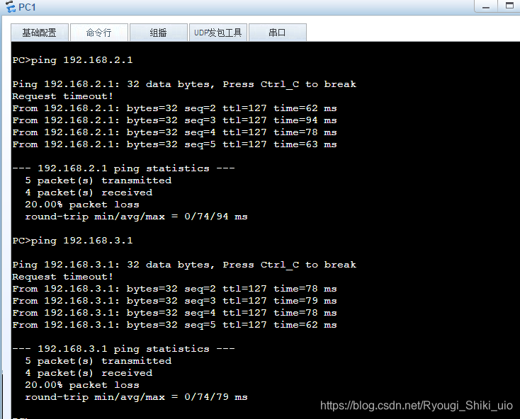
然后PC1与PC2,PC3ping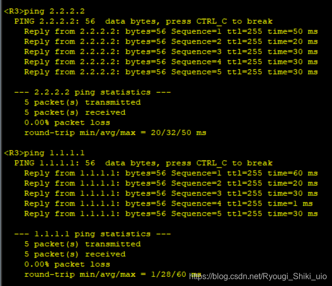
实验二

首先配好各个pc的ip地址,配好pc4,pc6的ip,子网掩码,网关。
sw1的配置
<Huawei>sys
Enter system view, return user view with Ctrl+Z.
[Huawei]sys sw1
[sw1]
[sw1]interface e0/0/1
[sw1-Ethernet0/0/1]
[sw1-Ethernet0/0/1]port link-type access
[sw1-Ethernet0/0/1]port default vlan 10
[sw1-Ethernet0/0/1]dis this
#
interface Ethernet0/0/1port link-type accessport default vlan 10
#
return
[sw1-Ethernet0/0/1]
[sw1-Ethernet0/0/1]interface e 0/0/2
[sw1-Ethernet0/0/2]port link-type access
[sw1-Ethernet0/0/2]port default vlan 20
[sw1-Ethernet0/0/2]
[sw1-Ethernet0/0/2]interface e0/0/3
[sw1-Ethernet0/0/3]port link-type access
[sw1-Ethernet0/0/3]port default vlan 10
[sw1-Ethernet0/0/3]
[sw1-Ethernet0/0/3]interface e0/0/5
[sw1-Ethernet0/0/5]port link-type access
[sw1-Ethernet0/0/5]port default vlan 20
[sw1-Ethernet0/0/5]dis this
#
interface Ethernet0/0/5port link-type accessport default vlan 20
#
return
[sw1-Ethernet0/0/5]port link-type access
[sw1-Ethernet0/0/5] port default vlan 20
[sw1-Ethernet0/0/5]interface e0/0/4
[sw1-Ethernet0/0/4]port link-type trunk
[sw1-Ethernet0/0/4]port trunk allow-pass vlan 10 20
sw2配置
<Huawei>sys
Enter system view, return user view with Ctrl+Z.
[Huawei]sys sw2
[sw2]
[sw2]interface e0/0/1
[sw2-Ethernet0/0/1]port link-type trunk
[sw2-Ethernet0/0/1]
[sw2-Ethernet0/0/1]dis this
#
interface Ethernet0/0/1port link-type trunk
#
return
[sw2-Ethernet0/0/1]port trunk allow-pass vlan 10 20
[sw2-Ethernet0/0/1]dis this
#
interface Ethernet0/0/1port link-type trunkport trunk allow-pass vlan 10 20
#
return
[sw2-Ethernet0/0/1]interface e0/0/2
[sw2-Ethernet0/0/2]port link-type access
[sw2-Ethernet0/0/2]prot
[sw2-Ethernet0/0/2]dis this
#
interface Ethernet0/0/2port link-type access
#
return
[sw2-Ethernet0/0/2]q
[sw2]vlan batch 10 20
Info: This operation may take a few seconds. Please wait for a moment...done.
[sw2]interface e0/0/2
[sw2-Ethernet0/0/2]port default vlan 20
[sw2-Ethernet0/0/2]
[sw2-Ethernet0/0/2]
[sw2-Ethernet0/0/2]dis this
#
interface Ethernet0/0/2port link-type accessport default vlan 20
#
return
[sw2-Ethernet0/0/2]
[sw2-Ethernet0/0/2]interface e0/0/3
[sw2-Ethernet0/0/3]port link-type access
[sw2-Ethernet0/0/3]port default vlan 10
[sw2-Ethernet0/0/3]dis this
#
interface Ethernet0/0/3port link-type accessport default vlan 10
#
return
r1配置
<Huawei>sys
Enter system view, return user view with Ctrl+Z.
[Huawei]sys r1
[r1]interface g0/0/0
[r1-GigabitEthernet0/0/0]ip address 192.168.2.254 24
Apr  6 2021 17:12:56-08:00 r1 %%01IFNET/4/LINK_STATE(l)[0]:The line protocol IP
on the interface GigabitEthernet0/0/0 has entered the UP state.
[r1-GigabitEthernet0/0/0]interface g0/0/1
[r1-GigabitEthernet0/0/1]ip address 192.168.20.1 24
Apr  6 2021 17:13:12-08:00 r1 %%01IFNET/4/LINK_STATE(l)[1]:The line protocol IP
on the interface GigabitEthernet0/0/1 has entered the UP state.
[r1-GigabitEthernet0/0/1]q
[r1]ip route-static 192.168.10.0 24 192.168.20.2
r2配置
<Huawei>sys
Enter system view, return user view with Ctrl+Z.
[Huawei]sys r2
[r2]interface g0/0/0
[r2-GigabitEthernet0/0/0]ip address 192.168.20.2 24
Apr  6 2021 17:13:36-08:00 r2 %%01IFNET/4/LINK_STATE(l)[0]:The line protocol IP
on the interface GigabitEthernet0/0/0 has entered the UP state.
[r2-GigabitEthernet0/0/0]interface g0/0/1
[r2-GigabitEthernet0/0/1]ip address 192.168.10.254 24
Apr  6 2021 17:13:58-08:00 r2 %%01IFNET/4/LINK_STATE(l)[1]:The line protocol IP
on the interface GigabitEthernet0/0/1 has entered the UP state.
[r2-GigabitEthernet0/0/1]q
[r2]ip route-static 0.0.0.0 0 192.168.20.1
pc5pingpc1,pc3 pc4pingpc2,pingpc6

实验三

先配好pc1,pc2,pc3的ip,子网掩码,网关
sw1的配置
<Huawei>
<Huawei>sys
Enter system view, return user view with Ctrl+Z.
[Huawei]sys sw1
[sw1]vlan batch 10 20 30
Info: This operation may take a few seconds. Please wait for a moment...done.
[sw1]
[sw1]interface e0/0/1
[sw1-Ethernet0/0/1]port link-type access
[sw1-Ethernet0/0/1]port default vlan 10
[sw1-Ethernet0/0/1]dis this
#
interface Ethernet0/0/1port link-type accessport default vlan 10
#
return
[sw1-Ethernet0/0/1]interface e0/0/2
[sw1-Ethernet0/0/2]port link-type access
[sw1-Ethernet0/0/2]port default vlan 20
[sw1-Ethernet0/0/2]dis this
#
interface Ethernet0/0/2port link-type accessport default vlan 20
#
return
[sw1-Ethernet0/0/2]interface e0/0/3
[sw1-Ethernet0/0/3]port link-type access
[sw1-Ethernet0/0/3]port default vlan 30
[sw1-Ethernet0/0/3]dis this
#
interface Ethernet0/0/3port link-type accessport default vlan 30
#
return
[sw1-Ethernet0/0/3]
[sw1-Ethernet0/0/3]interface e0/0/4
[sw1-Ethernet0/0/4]port link-type trunk
[sw1-Ethernet0/0/4]dis this
#
interface Ethernet0/0/4port link-type trunk
#
return
[sw1-Ethernet0/0/4]
[sw1-Ethernet0/0/4]port trunk allow-pass vlan 10 20 30
[sw1-Ethernet0/0/4]
[sw1-Ethernet0/0/4]dis this
#
interface Ethernet0/0/4port link-type trunkport trunk allow-pass vlan 10 20 30
#
return
[sw1-Ethernet0/0/4]
r1配置
<Huawei>sys
Enter system view, return user view with Ctrl+Z.
[Huawei]sys r1
[r1]interface g0/0/0.1
[r1-GigabitEthernet0/0/0.1]ip address 192.168.1.254 24
[r1-GigabitEthernet0/0/0.1]dot1q termination vid 10
Apr  6 2021 15:52:28-08:00 r1 %%01IFNET/4/LINK_STATE(l)[1]:The line protocol IP
on the interface GigabitEthernet0/0/0.1 has entered the UP state.
[r1-GigabitEthernet0/0/0.1]arp broadcast enable
[r1-GigabitEthernet0/0/0.1]interface g0/0/0.2
[r1-GigabitEthernet0/0/0.2]dot1q termination vid 20
[r1-GigabitEthernet0/0/0.2]arp broadcast enable
[r1-GigabitEthernet0/0/0.2]ip address 192.168.2.254 24
Apr  6 2021 15:53:23-08:00 r1 %%01IFNET/4/LINK_STATE(l)[2]:The line protocol IP
on the interface GigabitEthernet0/0/0.2 has entered the UP state.
[r1-GigabitEthernet0/0/0.2]interface g0/0/0.3
[r1-GigabitEthernet0/0/0.3]ip address 192.168.3.254 24
[r1-GigabitEthernet0/0/0.3]arp broadcast enable
Error: This interface is not a termination interface.
[r1-GigabitEthernet0/0/0.3]dot1q termination vid 30
Apr  6 2021 15:53:56-08:00 r1 %%01IFNET/4/LINK_STATE(l)[3]:The line protocol IP
on the interface GigabitEthernet0/0/0.3 has entered the UP state.
[r1-GigabitEthernet0/0/0.3]arp broadcast enable
[r1-GigabitEthernet0/0/0.3]
pc1pingpc2,pingpc3
这篇关于loopback地址,静态vlan,trunk的介绍,附实验题的文章就介绍到这儿,希望我们推荐的文章对编程师们有所帮助!


