What is an Alternate Setting? Example of device that needs them?
The USB spec has a lot of talk about them, but never tells what one is and - most importantly - why I would use one. I never saw a USB device that uses alternate settings.
本文主要是介绍usb alternate settings,希望对大家解决编程问题提供一定的参考价值,需要的开发者们随着小编来一起学习吧!
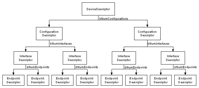
All USB devices have a hierarchy of descriptors which describe to the host information such as what the device is, who makes it, what version of USB it supports, how many ways it can be configured, the number of endpoints and their types etc
The more common USB descriptors are
USB devices can only have one device descriptor. The device descriptor includes information such as what USB revision the device complies to, the Product and Vendor IDs used to load the appropriate drivers and the number of possible configurations the device can have. The number of configurations indicate how many configuration descriptors branches are to follow.
The configuration descriptor specifies values such as the amount of power this particular configuration uses, if the device is self or bus powered and the number of interfaces it has. When a device is enumerated, the host reads the device descriptors and can make a decision of which configuration to enable. It can only enable one configuration at a time.
For example, It is possible to have a high power bus powered configuration and a self powered configuration. If the device is plugged into a host with a mains power supply, the device driver may choose to enable the high power bus powered configuration enabling the device to be powered without a connection to the mains, yet if it is connected to a laptop or personal organiser it could enable the 2nd configuration (self powered) requiring the user to plug your device into the power point.
The configuration settings are not limited to power differences. Each configuration could be powered in the same way and draw the same current, yet have different interface or endpoint combinations. However it should be noted that changing the configuration requires all activity on each endpoint to stop. While USB offers this flexibility, very few devices have more than 1 configuration.

The interface descriptor could be seen as a header or grouping of the endpoints into a functional group performing a single feature of the device. For example you could have a multi-function fax/scanner/printer device. Interface descriptor one could describe the endpoints of the fax function, Interface descriptor two the scanner function and Interface descriptor three the printer function. Unlike the configuration descriptor, there is no limitation as to having only one interface enabled at a time. A device could have 1 or many interface descriptors enabled at once.
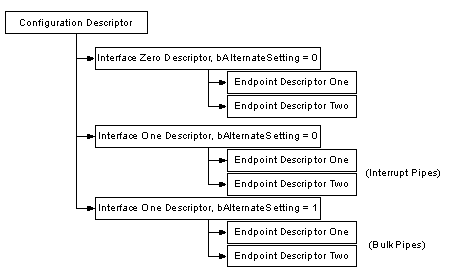
Interface descriptors have a bInterfaceNumber field specifying the Interface number and a bAlternateSetting which allows an interface to change settings on the fly. For example we could have a device with two interfaces, interface one and interface two. Interface one has bInterfaceNumber set to zero indicating it is the first interface descriptor and abAlternativeSetting of zero.
Interface two would have a bInterfaceNumber set to one indicating it is the second interface and a bAlternativeSettingof zero (default). We could then throw in another descriptor, also with a bInterfaceNumber set to one indicating it is the second interface, but this time setting the bAlternativeSetting to one, indicating this interface descriptor can be an alternative setting to that of the other interface descriptor two.
When this configuration is enabled, the first two interface descriptors with bAlternativeSettings equal to zero is used. However during operation the host can send a SetInterface request directed to that of Interface one with a alternative setting of one to enable the other interface descriptor.

This gives an advantage over having two configurations, in that we can be transmitting data over interface zero while we change the endpoint settings associated with interface one without effecting interface zero.
Each endpoint descriptor is used to specify the type of transfer, direction, polling interval and maximum packet size for each endpoint. Endpoint zero, the default control endpoint is always assumed to be a control endpoint and as such never has a descriptor.
All descriptors are made up of a common format. The first byte specifies the length of the descriptor, while the second byte indicates the descriptor type. If the length of a descriptor is smaller than what the specification defines, then the host shall ignore it. However if the size is greater than expected the host will ignore the extra bytes and start looking for the next descriptor at the end of actual length returned.
| Offset | Field | Size | Value | Description |
| 0 | bLength | 1 | Number | Size of Descriptor in Bytes |
| 1 | bDescriptionType | 1 | Constant | DescriptorType |
| 2 | ... | n | Start of parameters for descriptor |
The device descriptor of a USB device represents the entire device. As a result a USB device can only have one device descriptor. It specifies some basic, yet important information about the device such as the supported USB version, maximum packet size, vendor and product IDs and the number of possible configurations the device can have. The format of the device descriptor is shown below.
| Offset | Field | Size | Value | Description |
| 0 | bLength | 1 | Number | Size of the Descriptor in Bytes (18 bytes) |
| 1 | bDescriptorType | 1 | Constant | Device Descriptor (0x01) |
| 2 | bcdUSB | 2 | BCD | USB Specification Number which device complies too. |
| 4 | bDeviceClass | 1 | Class | Class Code (Assigned by USB Org) If equal to Zero, each interface specifies it’s own class code If equal to 0xFF, the class code is vendor specified. Otherwise field is valid Class Code. |
| 5 | bDeviceSubClass | 1 | SubClass | Subclass Code (Assigned by USB Org) |
| 6 | bDeviceProtocol | 1 | Protocol | Protocol Code (Assigned by USB Org) |
| 7 | bMaxPacketSize | 1 | Number | Maximum Packet Size for Zero Endpoint. Valid Sizes are 8, 16, 32, 64 |
| 8 | idVendor | 2 | ID | Vendor ID (Assigned by USB Org) |
| 10 | idProduct | 2 | ID | Product ID (Assigned by Manufacturer) |
| 12 | bcdDevice | 2 | BCD | Device Release Number |
| 14 | iManufacturer | 1 | Index | Index of Manufacturer String Descriptor |
| 15 | iProduct | 1 | Index | Index of Product String Descriptor |
| 16 | iSerialNumber | 1 | Index | Index of Serial Number String Descriptor |
| 17 | bNumConfigurations | 1 | Integer | Number of Possible Configurations |
The bcdUSB field reports the highest version of USB the device supports. The value is in binary coded decimal with a format of 0xJJMN where JJ is the major version number, M is the minor version number and N is the sub minor version number. e.g. USB 2.0 is reported as 0x0200, USB 1.1 as 0x0110 and USB 1.0 as 0x0100.
The bDeviceClass, bDeviceSubClass and bDeviceProtocol are used by the operating system to find a class driver for your device. Typically only the bDeviceClass is set at the device level. Most class specifications choose to identify itself at the interface level and as a result set the bDeviceClass as 0x00. This allows for the one device to support multiple classes.
The bMaxPacketSize field reports the maximum packet size for endpoint zero. All devices must support endpoint zero.
The idVendor and idProduct are used by the operating system to find a driver for your device. The Vendor ID is assigned by the USB-IF.
The bcdDevice has the same format than the bcdUSB and is used to provide a device version number. This value is assigned by the developer.
Three string descriptors exist to provide details of the manufacturer, product and serial number. There is no requirement to have string descriptors. If no string descriptor is present, a index of zero should be used.
bNumConfigurations defines the number of configurations the device supports at its current speed.
A USB device can have several different configurations although the majority of devices are simple and only have one. The configuration descriptor specifies how the device is powered, what the maximum power consumption is, the number of interfaces it has. Therefore it is possible to have two configurations, one for when the device is bus powered and another when it is mains powered. As this is a "header" to the Interface descriptors, its also feasible to have one configuration using a different transfer mode to that of another configuration.
Once all the configurations have been examined by the host, the host will send a SetConfiguration command with a non zero value which matches the bConfigurationValue of one of the configurations. This is used to select the desired configuration.
| Offset | Field | Size | Value | Description |
| 0 | bLength | 1 | Number | Size of Descriptor in Bytes |
| 1 | bDescriptorType | 1 | Constant | Configuration Descriptor (0x02) |
| 2 | wTotalLength | 2 | Number | Total length in bytes of data returned |
| 4 | bNumInterfaces | 1 | Number | Number of Interfaces |
| 5 | bConfigurationValue | 1 | Number | Value to use as an argument to select this configuration |
| 6 | iConfiguration | 1 | Index | Index of String Descriptor describing this configuration |
| 7 | bmAttributes | 1 | Bitmap | D7 Reserved, set to 1. (USB 1.0 Bus Powered) D6 Self Powered D5 Remote Wakeup D4..0 Reserved, set to 0. |
| 8 | bMaxPower | 1 | mA | Maximum Power Consumption in 2mA units |
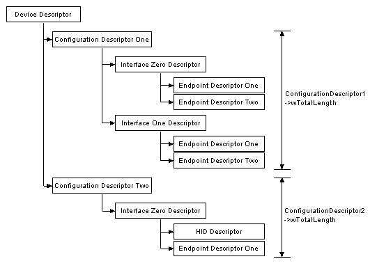
When the configuration descriptor is read, it returns the entire configuration hierarchy which includes all related interface and endpoint descriptors. The wTotalLength field reflects the number of bytes in the hierarchy.

bNumInterfaces specifies the number of interfaces present for this configuration.
bConfigurationValue is used by the SetConfiguration request to select this configuration.
iConfiguration is a index to a string descriptor describing the configuration in human readable form.
bmAttributes specify power parameters for the configuration. If a device is self powered, it sets D6. Bit D7 was used in USB 1.0 to indicate a bus powered device, but this is now done by bMaxPower. If a device uses any power from the bus, whether it be as a bus powered device or as a self powered device, it must report its power consumption in bMaxPower. Devices can also support remote wakeup which allows the device to wake up the host when the host is in suspend.
bMaxPower defines the maximum power the device will drain from the bus. This is in 2mA units, thus a maximum of approximately 500mA can be specified. The specification allows a high powered bus powered device to drain no more than 500mA from Vbus. If a device loses external power, then it must not drain more than indicated in bMaxPower. It should fail any operation it cannot perform without external power.
The interface descriptor could be seen as a header or grouping of the endpoints into a functional group performing a single feature of the device. The interface descriptor conforms to the following format,
| Offset | Field | Size | Value | Description |
| 0 | bLength | 1 | Number | Size of Descriptor in Bytes (9 Bytes) |
| 1 | bDescriptorType | 1 | Constant | Interface Descriptor (0x04) |
| 2 | bInterfaceNumber | 1 | Number | Number of Interface |
| 3 | bAlternateSetting | 1 | Number | Value used to select alternative setting |
| 4 | bNumEndpoints | 1 | Number | Number of Endpoints used for this interface |
| 5 | bInterfaceClass | 1 | Class | Class Code (Assigned by USB Org) |
| 6 | bInterfaceSubClass | 1 | SubClass | Subclass Code (Assigned by USB Org) |
| 7 | bInterfaceProtocol | 1 | Protocol | Protocol Code (Assigned by USB Org) |
| 8 | iInterface | 1 | Index | Index of String Descriptor Describing this interface |
bInterfaceNumber indicates the index of the interface descriptor. This should be zero based, and incremented once for each new interface descriptor.
bAlternativeSetting can be used to specify alternative interfaces. These alternative interfaces can be selected with the Set Interface request.
bNumEndpoints indicates the number of endpoints used by the interface. This value should exclude endpoint zero and is used to indicate the number of endpoint descriptors to follow.
bInterfaceClass, bInterfaceSubClass and bInterfaceProtocol can be used to specify supported classes (e.g. HID, communications, mass storage etc.) This allows many devices to use class drivers preventing the need to write specific drivers for your device.
iInterface allows for a string description of the interface.
Endpoint descriptors are used to describe endpoints other than endpoint zero. Endpoint zero is always assumed to be a control endpoint and is configured before any descriptors are even requested. The host will use the information returned from these descriptors to determine the bandwidth requirements of the bus.
| Offset | Field | Size | Value | Description |
| 0 | bLength | 1 | Number | Size of Descriptor in Bytes (7 bytes) |
| 1 | bDescriptorType | 1 | Constant | Endpoint Descriptor (0x05) |
| 2 | bEndpointAddress | 1 | Endpoint | Endpoint Address Bits 0..3b Endpoint Number. Bits 4..6b Reserved. Set to Zero Bits 7 Direction 0 = Out, 1 = In (Ignored for Control Endpoints) |
| 3 | bmAttributes | 1 | Bitmap | Bits 0..1 Transfer Type
Bits 3..2 = Synchronisation Type (Iso Mode)
|
| 4 | wMaxPacketSize | 2 | Number | Maximum Packet Size this endpoint is capable of sending or receiving |
| 6 | bInterval | 1 | Number | Interval for polling endpoint data transfers. Value in frame counts. Ignored for Bulk & Control Endpoints. Isochronous must equal 1 and field may range from 1 to 255 for interrupt endpoints. |
bEndpointAddress indicates what endpoint this descriptor is describing.
bmAttributes specifies the transfer type. This can either be Control, Interrupt, Isochronous or Bulk Transfers. If an Isochronous endpoint is specified, additional attributes can be selected such as the Synchronisation and usage types.
wMaxPacketSize indicates the maximum payload size for this endpoint.
bInterval is used to specify the polling interval of certain transfers. The units are expressed in frames, thus this equates to either 1ms for low/full speed devices and 125us for high speed devices.
String descriptors provide human readable information and are optional. If they are not used, any string index fields of descriptors must be set to zero indicating there is no string descriptor available.
The strings are encoded in the Unicode format and products can be made to support multiple languages. String Index 0 should return a list of supported languages. A list of USB Language IDs can be found in Universal Serial Bus Language Identifiers (LANGIDs) version 1.0
| Offset | Field | Size | Value | Description |
| 0 | bLength | 1 | Number | Size of Descriptor in Bytes |
| 1 | bDescriptorType | 1 | Constant | String Descriptor (0x03) |
| 2 | wLANGID[0] | 2 | number | Supported Language Code Zero |
| 4 | wLANGID[1] | 2 | number | Supported Language Code One |
| n | wLANGID[x] | 2 | number | Supported Language Code x |
The above String Descriptor shows the format of String Descriptor Zero. The host should read this descriptor to determine what languages are available. If a language is supported, it can then be referenced by sending the language ID in the wIndex field of a Get Descriptor(String) request.
All subsequent strings take on the format below,
| Offset | Field | Size | Value | Description |
| 0 | bLength | 1 | Number | Size of Descriptor in Bytes |
| 1 | bDescriptorType | 1 | Constant | String Descriptor (0x03) |
| 2 | bString | n | Unicode | Unicode Encoded String |

| up vote 0 down vote favorite | What is an Alternate Setting? Example of device that needs them? The USB spec has a lot of talk about them, but never tells what one is and - most importantly - why I would use one. I never saw a USB device that uses alternate settings. usb | ||
| add a comment |
| up vote 2 down vote | The alternate setting of a You can look at this link for more details. |
这篇关于usb alternate settings的文章就介绍到这儿,希望我们推荐的文章对编程师们有所帮助!
http://www.chinasem.cn/article/182378。
23002807@qq.com